Visual Servoing Platform  version 3.6.1 under development (2024-03-29)
Tutorial: How to use Blender to generate simulated data for model-based tracking experiments

Introduction

This tutorial will show how to use Blender, a free and open source 3D creation suite, to create a simple textured object like a tee box, generate color and depth images from a virtual RGB-D camera, retrieve color and depth camera intrinsics and get ground truth color camera poses while the RGB-D camera is animated.

Once generated by Blender, data could be used by the model-based tracker and results could be compared with ground truth.

This tutorial was tested Ubuntu and macOS with the following versions:

OS Blender
Ubuntu 22.04 Blender 3.6.4
macOS Ventura 13.6 Blender 3.4.1
Warning
You are advised to know how to use the basic tools of Blender before reading this tutorial. Some non-exhaustive links:

Note that all the material (source code, input video, CAD model or XML settings files) described in this tutorial is part of ViSP source code (in tracking/model-based/generic-rgbd-blender folder) and could be found in https://github.com/lagadic/visp/tree/master/tracking/model-based/generic-rgbd-blender.

Considered setup

Remember that for each object considered by the model-based tracker, you need a Tracker CAD model (object_name.cao or object_name.wrl) and a file for Tracker initialization by mouse click (object_name.init).

Tea box objet

In this tutorial we will consider a tea box. The CAD model file (teabox.cao) and the init file (teabox.init) are provided in model/teabox folder:

$ cd $VISP_WS/visp-build/tutorial/tracking/model-based/generic-rgbd-blender
$ ls model/teabox/teabox
teabox.cao teabox.png teabox_color.xml
teabox.init teabox.wrl teabox_depth.xml

Instead of creating an object with any dimensions, to simplify this tutorial, in Blender we'll create a tea box whose dimensions, object frame, and 3D point coordinates correspond to those in the teabox.cao and teabox.init.

Note
If you are not familiar with these files and their content, you may follow Tutorial: Markerless generic model-based tracking using a color camera.

The content of the teabox.cao file is the following:

1 V1
2 # 3D Points
3 8 # Number of points
4 0 0 0 # Point 0: X Y Z
5 0 0 -0.08 # Point 1
6 0.165 0 -0.08 # Point 2
7 0.165 0 0 # Point 3
8 0.165 0.068 0 # Point 4
9 0.165 0.068 -0.08 # Point 5
10 0 0.068 -0.08 # Point 6
11 0 0.068 0 # Point 7
12 # 3D Lines
13 0 # Number of lines
14 # Faces from 3D lines
15 0 # Number of faces
16 # Faces from 3D points
17 6 # Number of faces
18 4 0 1 2 3 # Face 0: [number of points] [index of the 3D points]...
19 4 1 6 5 2
20 4 4 5 6 7
21 4 0 3 4 7
22 4 5 4 3 2
23 4 0 7 6 1 # Face 5
24 # 3D cylinders
25 0 # Number of cylinders
26 # 3D circles
27 0 # Number of circles

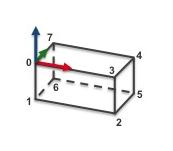
The corresponding CAD model is the following:

Analysing teabox.cao we can see that the box dimensions are the following (see teabox.cao example):

  • Height (from point 0 to point 1): 0.08 meters
  • Length (from point 0 to point 3): 0.165 meters
  • Width (from point 0 to point 7): 0.068 meters

RGB-D camera

We will also consider a RGB-D camera where the left camera is a classical color camera and the right camera a depth camera. The distance between left and right cameras is 10 cm. Both cameras are grabbing 640 x 480 images.

Camera Setting Values
Color Image resolution 640 x 480
Focal lenght 35 mm
Sensor size 32 mm x 24 mm
Depth Image resolution 640 x 480
Focal lenght 30 mm
Sensor size 32 mm x 24 mm
Note
In ViSP (see vpCameraParameters class) and in the computer vision community, camera intrinsic parameters are the following:

\[ {\bf K} = \begin{bmatrix} p_x & 0 & u_0 \\ 0 & p_y & v_0 \\ 0 & 0 & 1 \end{bmatrix} \]

where:
  • $ \left( p_x, p_y \right) $ corresponds to the pixel size
  • and $ \left( u_0, v_0 \right) $ to the principal point location.
The relations that links the pixel size with the focal lenght $ f $, the camera sensor size and the image resolution are the following:

\[ p_x = \frac{f \times \text{image width}}{\text{sensor width}} \]

\[ p_y = \frac{f \times \text{image height}}{\text{sensor height}} \]

Create your scene with Blender

In this section, we will create the corresponding tea box, RGB-D camera and define an initial and final RGB-D camera pose used to animate the scene.

Create tea box object

Here we will show how to create with Blender a box with the following dimensions:

  • Height: 0.08 meters
  • Length: 0.165 meters
  • Width: 0.068 meters

Open Blender and do the following to transform the cube in a box with the expected dimensions:

  • In "Object Mode" (1) select the "Cube" the right pannel (2). Edges should appear in orange
  • Deploy the "Transform" panel (3)
  • Set 
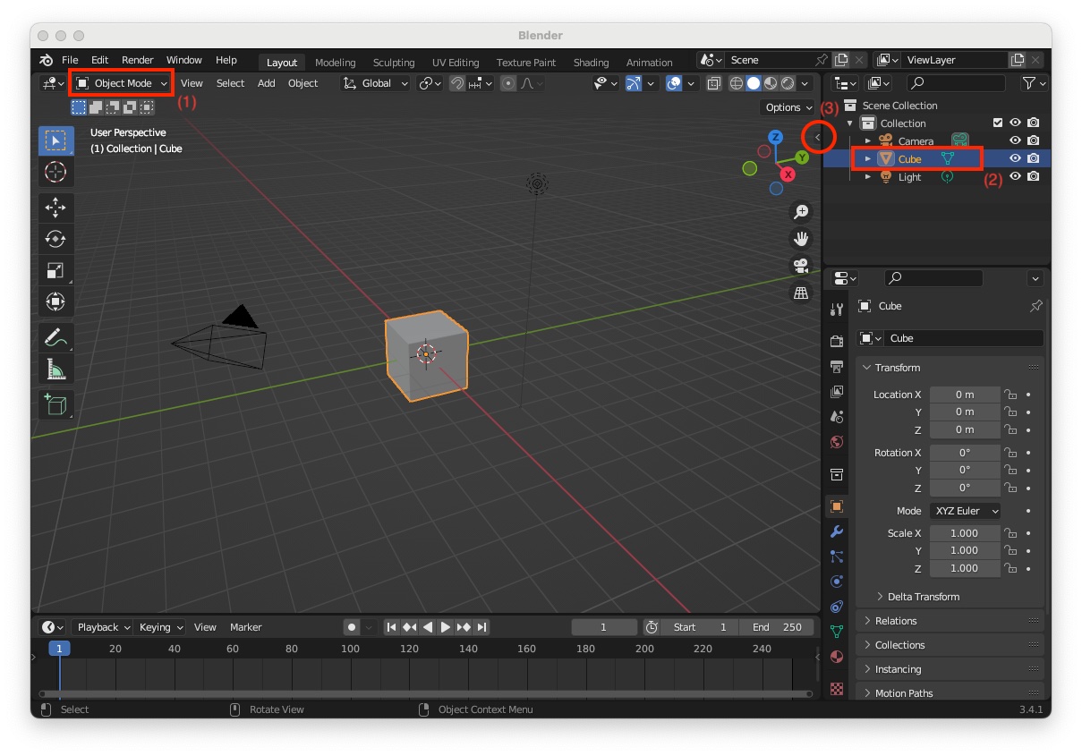
"Dimensions" to X=0.165, Y=0.068 and Z=0.08 meters (4) and change the object name to "teabox" (5). As the object's dimensions are drastically reduced, it becomes very small at the centre of the scene.
  • With the middle mouse button, zoom in to see the box, select the "teabox" object in this is not the case (6), and rescale the object to 1. To rescale, move the mouse pointer in the scene near the box, press shortcut: Ctrl-A and select "Apply > Scale". At this point, you should see that the scale values are set to 1 (7).

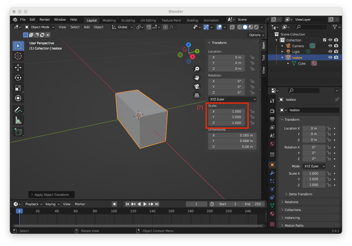
The coordinates of the box's vertices are expressed in the object frame which origin is at the box center of gravity (cog) and which axis are aligned with the scene reference frame. To conform with the required CAD model, we will move the origin of the object frame at point 0 which position is given in the next image:

  • select the "teabox" object in not the case, enter "Edit Mode" (8), select vertex corresponding to point 0 (9), press shortcut Shift-S and select "Cursor to Selected" (10)
  • As given in the next image, at point 0 you can now see the cursor (11). Switch to 
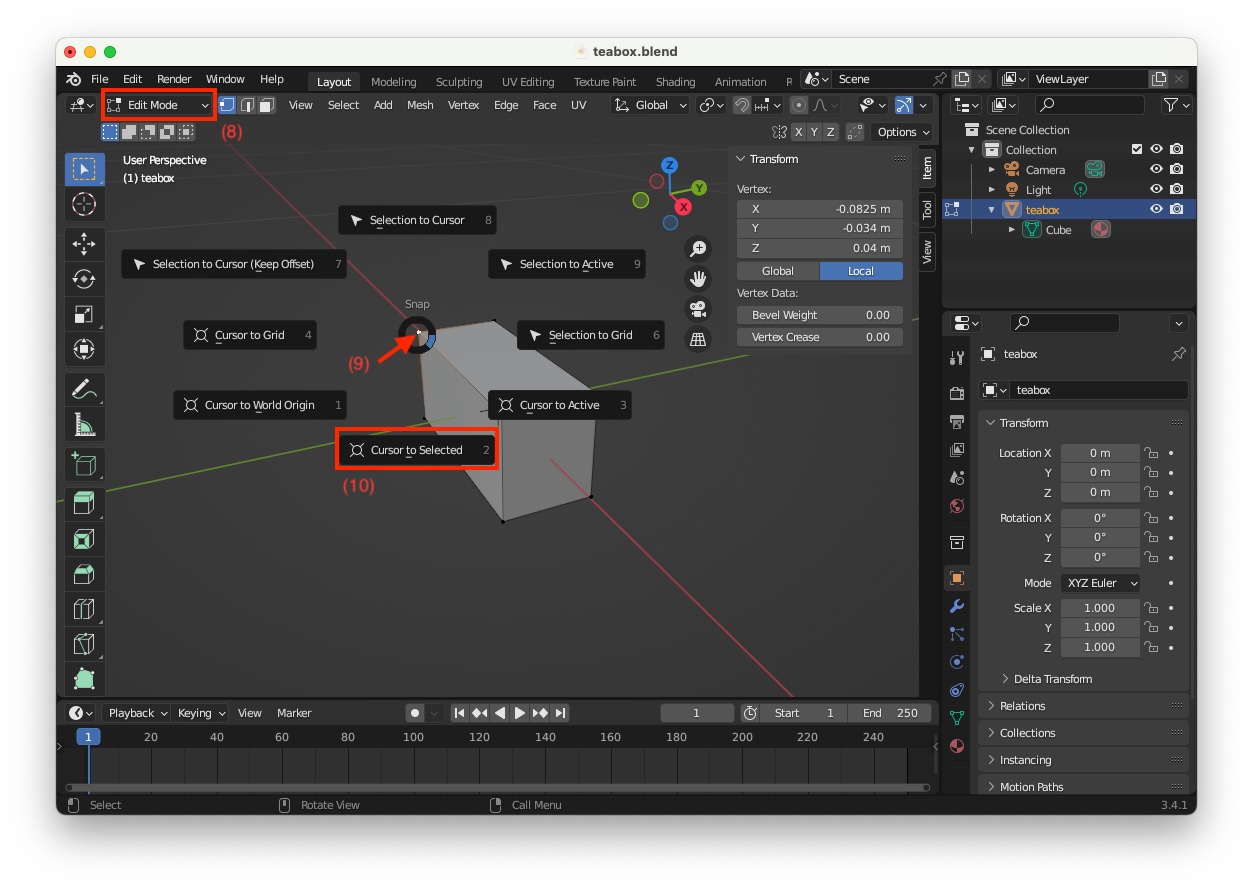
"Object Mode" (12), move the mouse pointer in the scene close to the box and press mouse right click to make appear "Object Context Menu". In this menu, select "Set Origin > Origin to 3D Cursor" (13)
  • Now you can verify that all the 8 vertices have the same 3D coordinates as the one in the required CAD model. For example, to get the 3D coordinates of point 3, switch to 
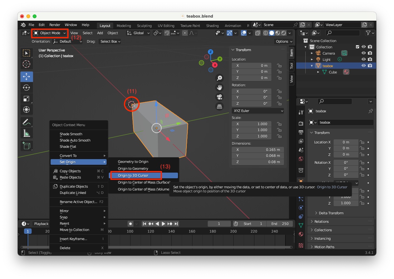
"Edit Mode" (14), select the corresponding vertex (15) to see its coordinates (16)
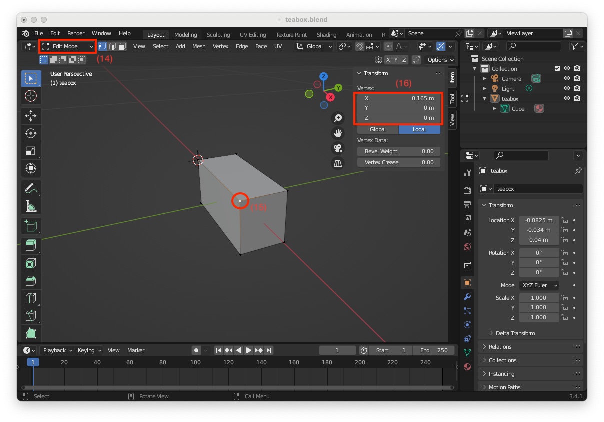
  • These coordinates are exactly the same as the one given in "teabox.cao" file
    0.165 0 0 # Point 3

Next step consists in adding a texture to be able to test tracking with keypoint features. You can add a realistic texture using an image texture, but here again, to simplify this tutorial, we will just add a "Voronoi Texture". To this end:

  • Switch to "Object Mode" (1)
  • Click on "Viewport Shading with Material Preview" icon (2)
  • Click on "Material Properties" icon (3)
  • Click on the yellow bullet at the right of "Base Color" (4)
  • Select 
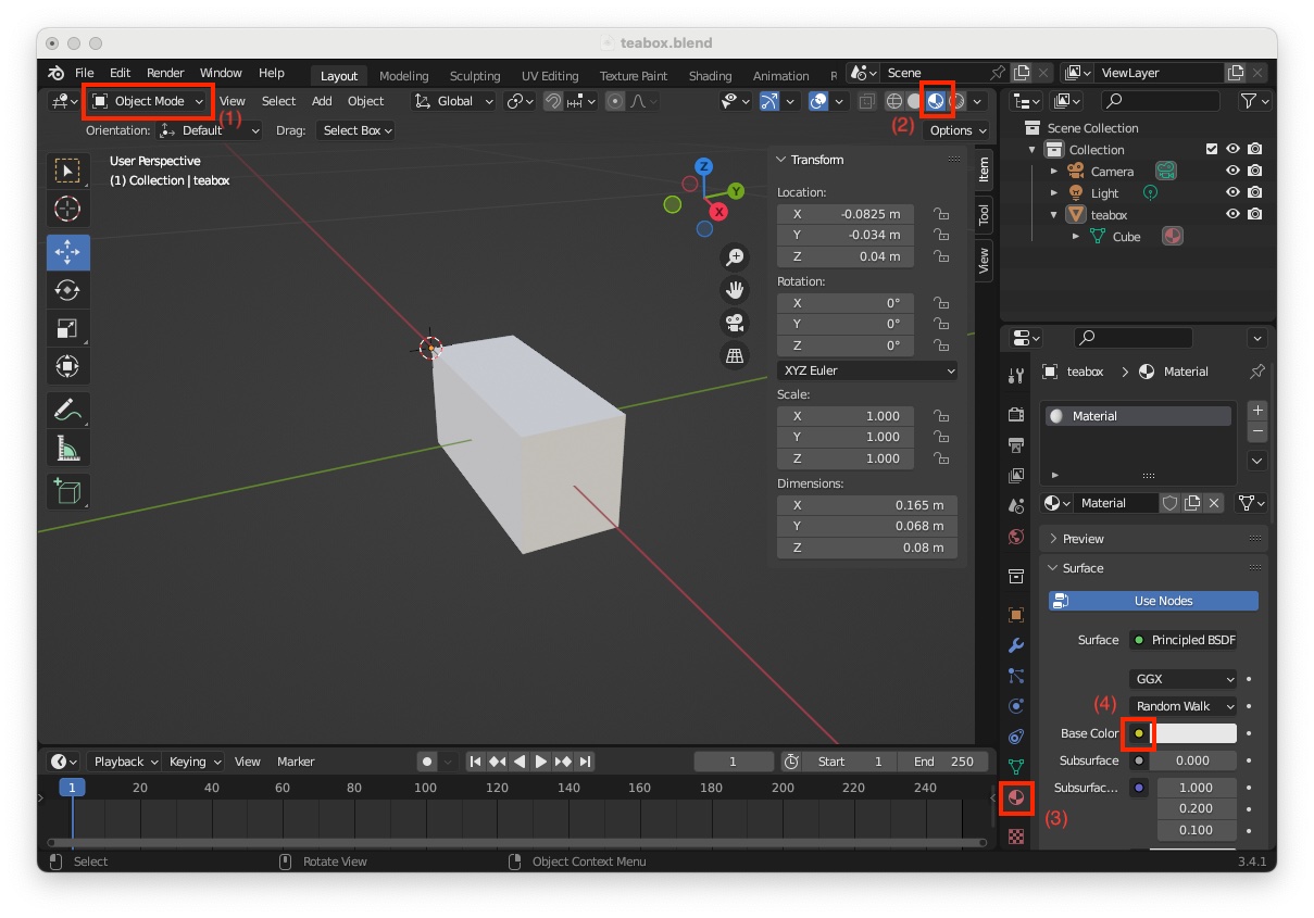
"Voronoi Texture" (5)
  • You can now see the texture applied to the box faces

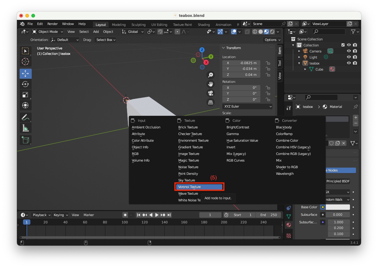
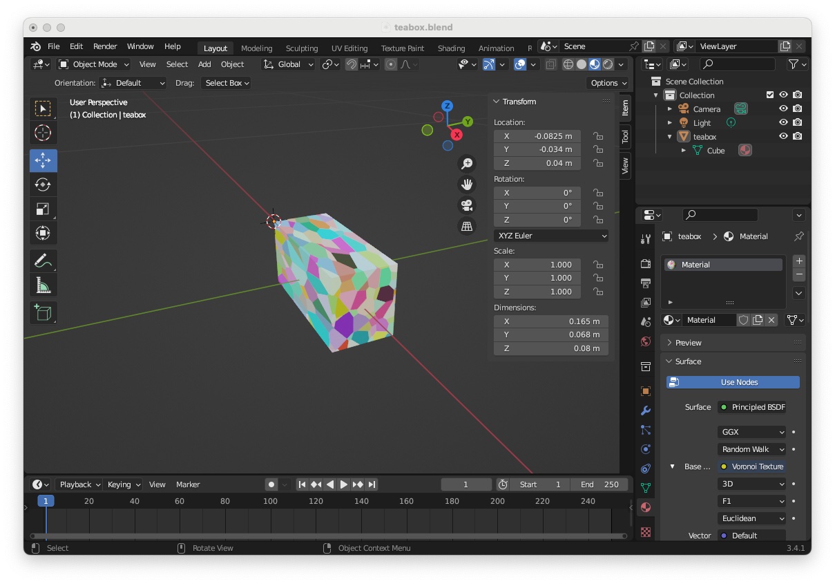
This ends the creation of a textured box that matches the "teabox.cao" cad model.

Color camera settings

Here you will set the color camera image resolution to 640x480 to match a VGA camera resolution, set the focal length to f = 35 mm, and the sensor size to 32 mm x 24 mm. Note that the width / height ratio must be the same for the image resolution and the sensor resolution. The values we use correspond to a ratio of 4/3.

We consider now that the "Camera" that is already in the scene is the left camera. To modify its settings:

  • Select the camera and rename it to "Camera_L" (1)
  • Select camera icon to access camera properties (2)
  • Change focal lenght to 35 mm (3)
  • Deploy "Camera" menu and change "Sensor Fit" to "Vertical" and set sensor"Width"to 32 mm and sensor "Height"` to 24 mm (4)

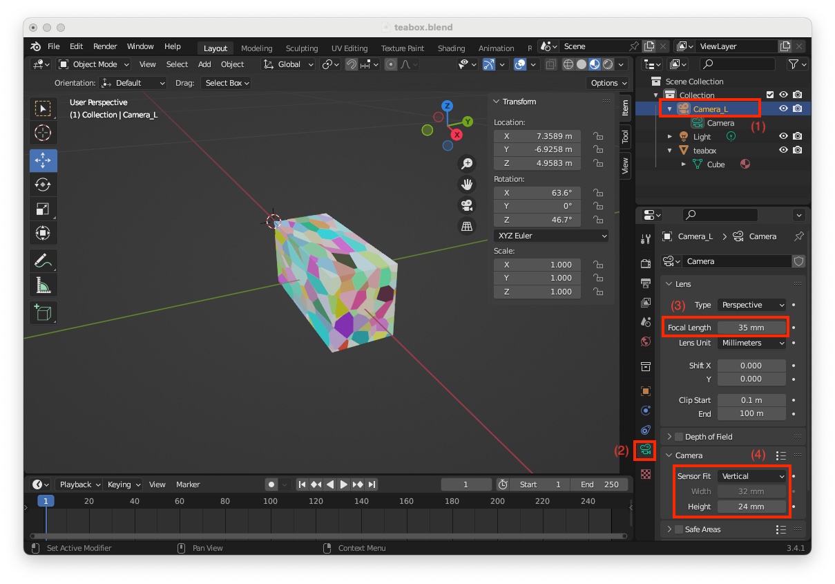
Now to set image resolution to 640x480

  • Select "Output Properties" icon (5)
  • Set "Resolution X" to 640 and "Resolution Y" to 480 (6)

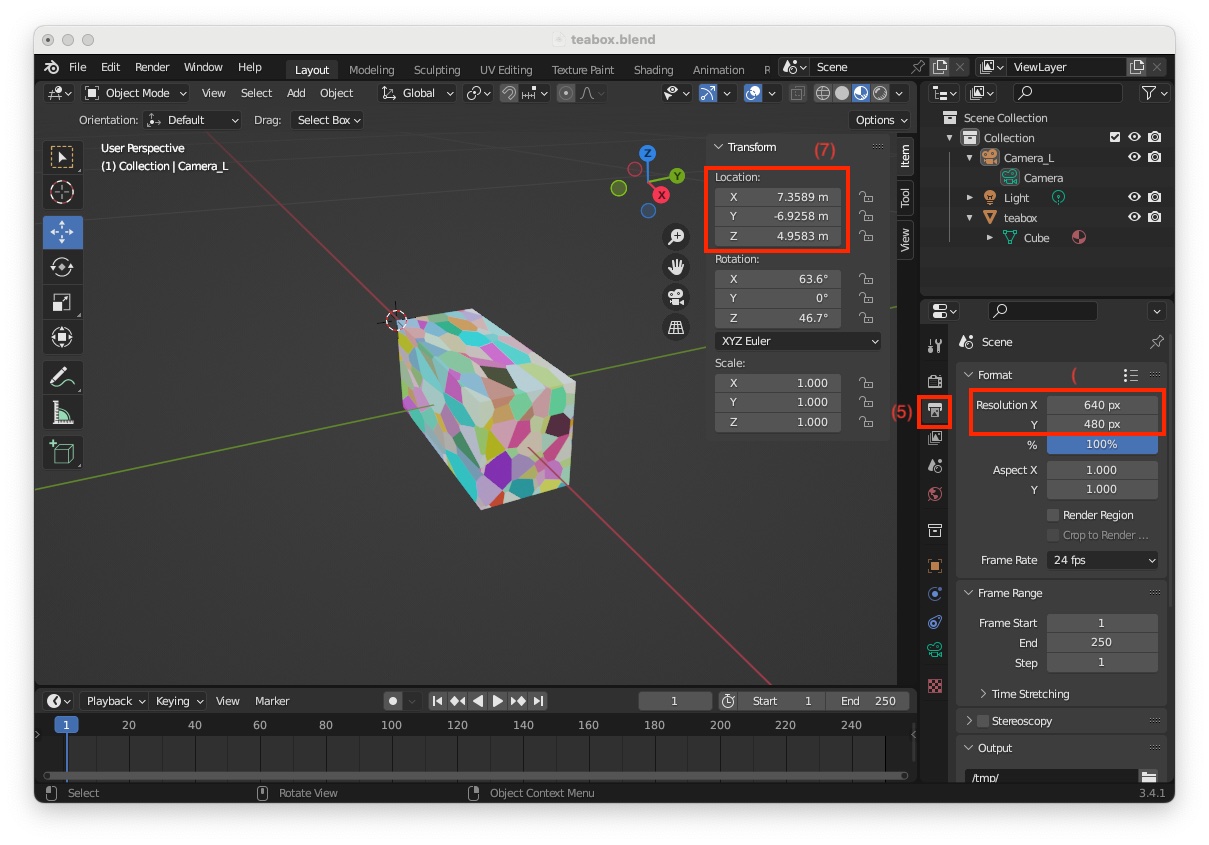
As shown in the previous image, the camera is not visible in the scene. This is simply due to its location that is too far from the scene origin. The camera frame origin is exactly at location X = 7.3589, Y = -6.9258, Z = 4.9583 meters (7). We need to move the camera close to the object and choose a position that will ease introduction of the depth camera.

To this end:

  • In the "Transform" panel, modify its "Location" to X = 0, Y = -0.35, Z = 0.3 meters, its "Rotation" to X = 45, Y = 0, Z = 0 deg, and its "Scale" to X = 0.050, Y = 0.050, Z = 0.050 (8)
  • Use the mouse middle button to zoom out in order to see the camera and the box

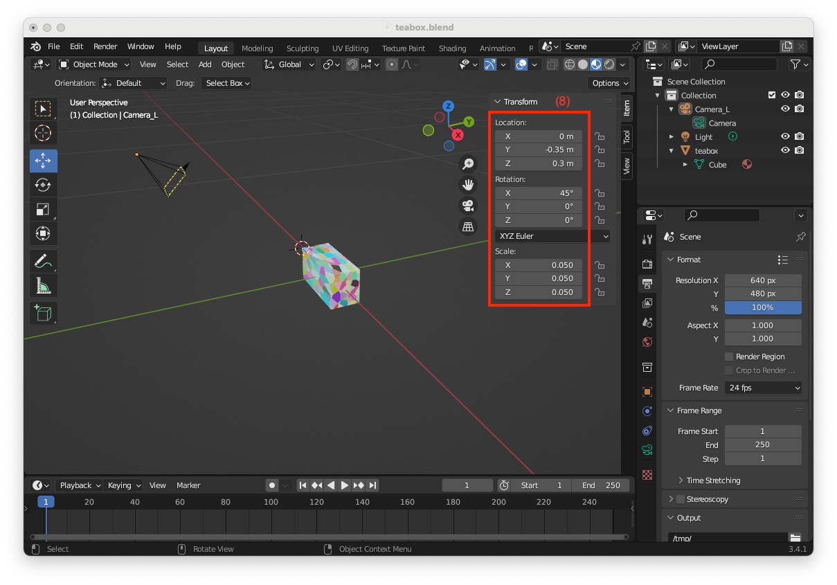
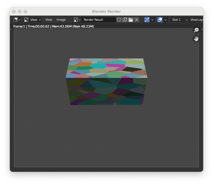
For curiosity you can now render an image of your object (shortcut: F12) and obtain an image like the following:

Add a depth camera

To simulate an RGB-D camera, we need to add a second camera to retrieve the depth map and set the appropriate parameters to match the desired intrinsic parameters following the same instructions as in previous section. To this end:

  • If not the case switch to "3D Viewport" (shortcut: Shift-F5)
  • Enter menu "Add > Camera" (1)
  • In the "Scene Collection" the new camera appears with name "Camera" (2)
  • Image resolution is already set to 640x480 (3)

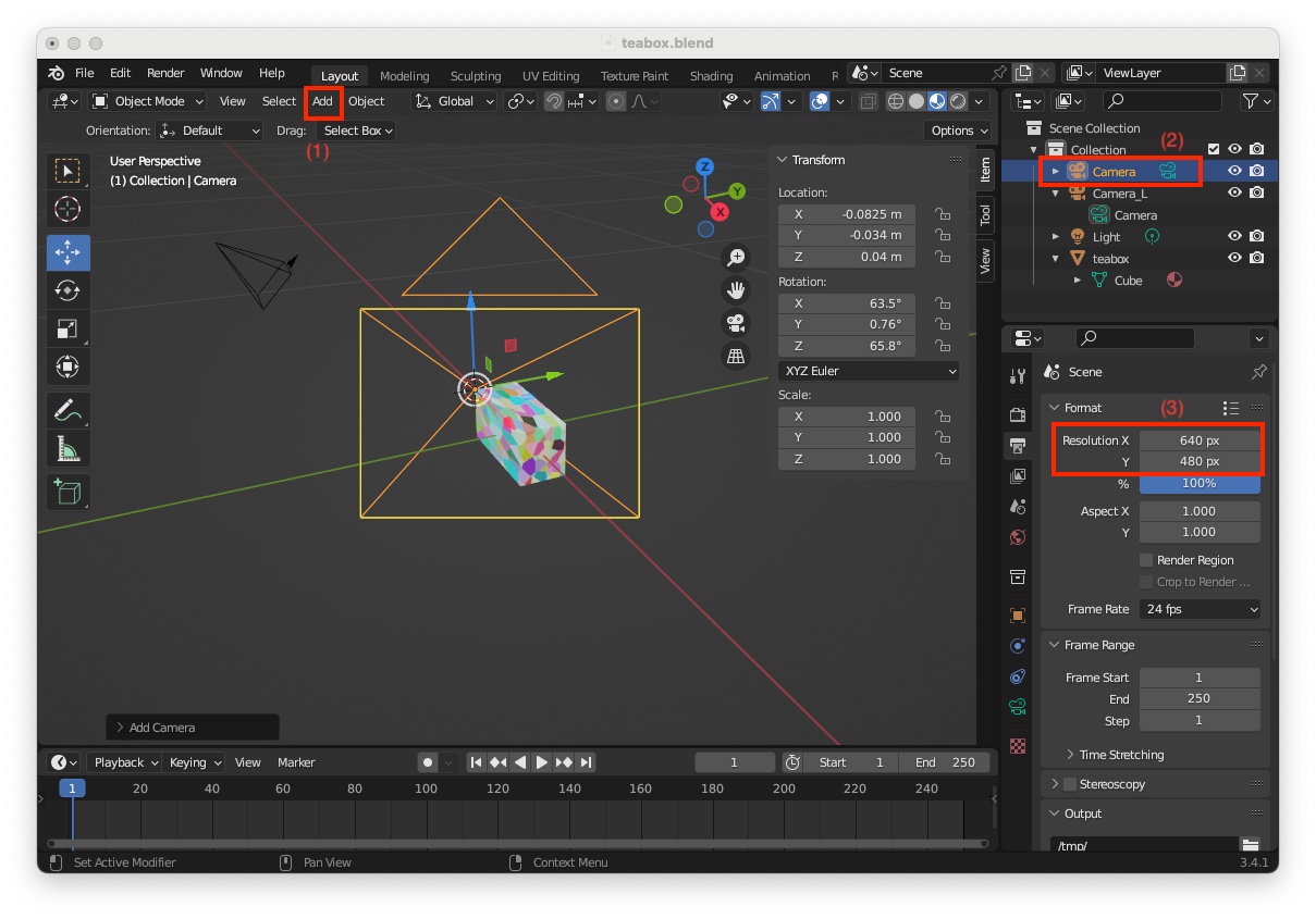
We need now to modify its settings to match the required intrinsics:

  • Rename the camera to "Camera_R" (4)
  • Click on camera icon (5)
  • Set its focal lenght to 30 mm (6) and sensor resolution to 32 mm x 24 mm (7)

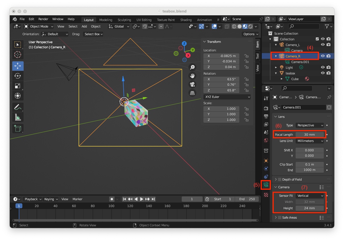
Since this depth camera should be 10 cm on the right of the color camera, we need to modify its location:

  • Be sure that the "Camera_R" corresponding to the depth camera is selected (8)
  • In the"Transform"panel, modify its"Location"to X = 0.1, Y = -0.35, Z = 0.3 meters, its"Rotation" to X = 45, Y = 0, Z = 0 deg, and its"Scale"` to X = 0.050, Y = 0.050, Z = 0.050 (9)

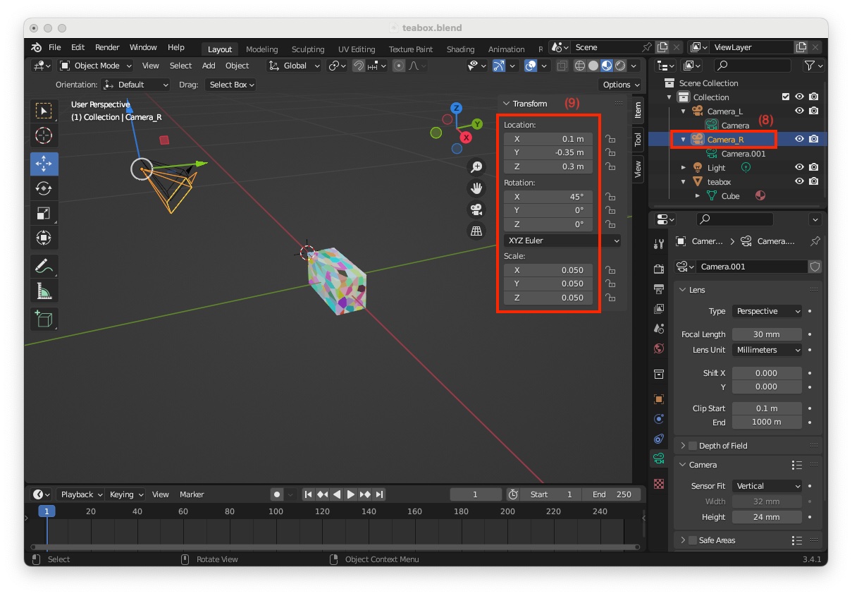
As we want to be able to animate the movement of the stereo pair rather than each camera individually, we need to link them together using the Blender parenting concept:

  • In the "Scene Collection" select "Camera_R" that will be the child object (10)
  • Press Ctrl key and select "Camera_L" that will be the parent object (11)
  • Right camera should become orange, while left camera yellow (12)
  • Hit shortcut Ctrl-P to parent them
  • Set parent to "Object" (13)
  • Once done, you can see that 
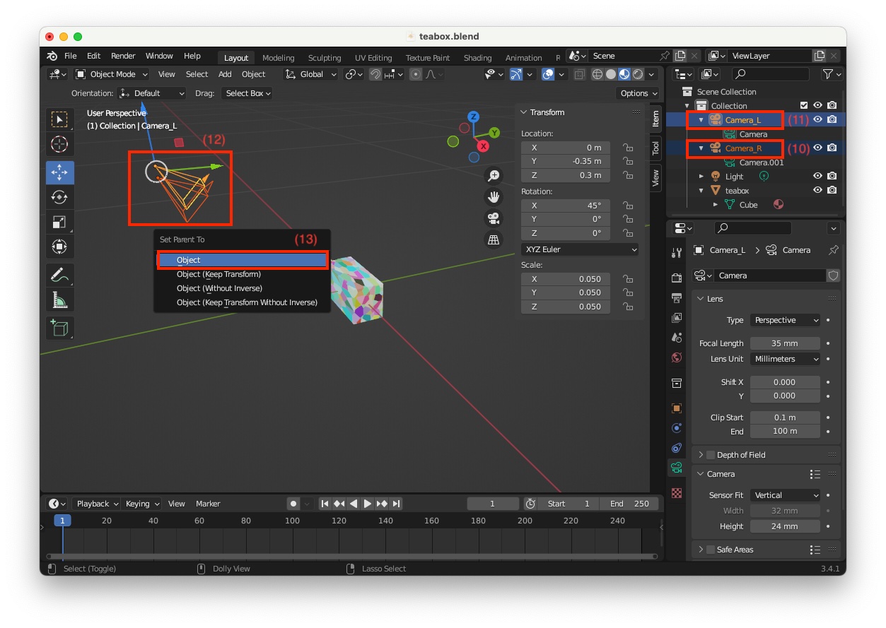
"Camera_L" has for child "Camera_L" (14)

Enable depth maps

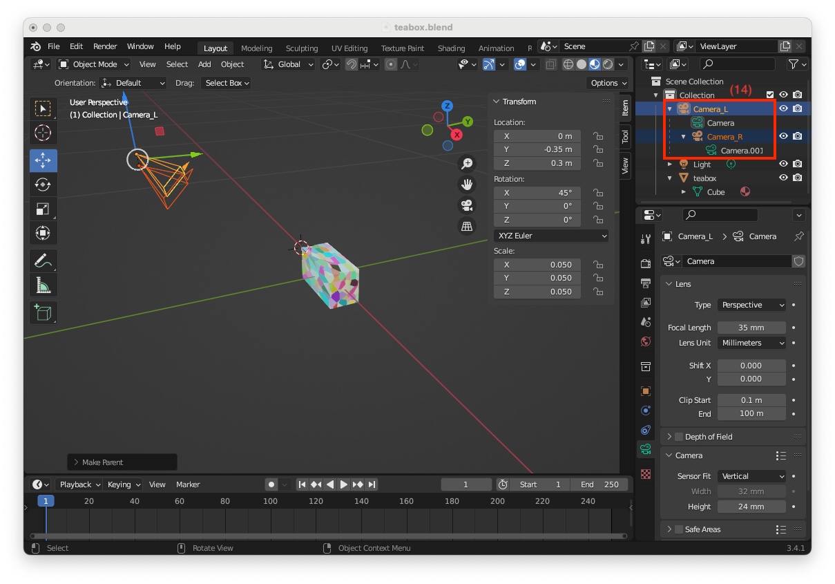
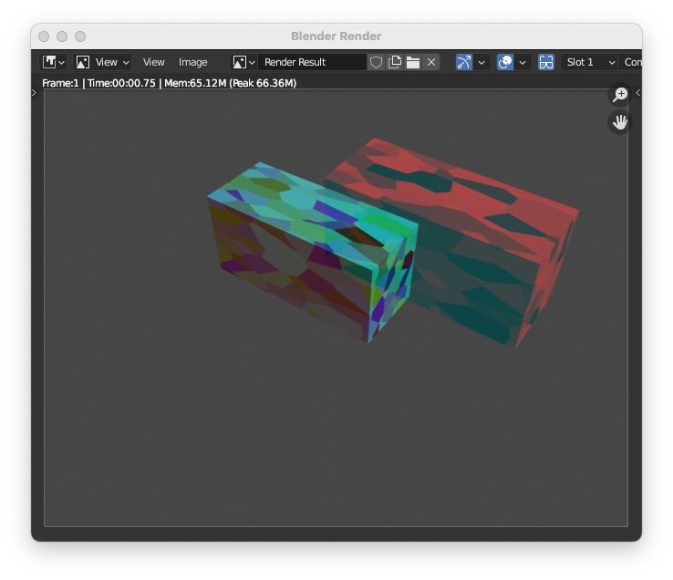
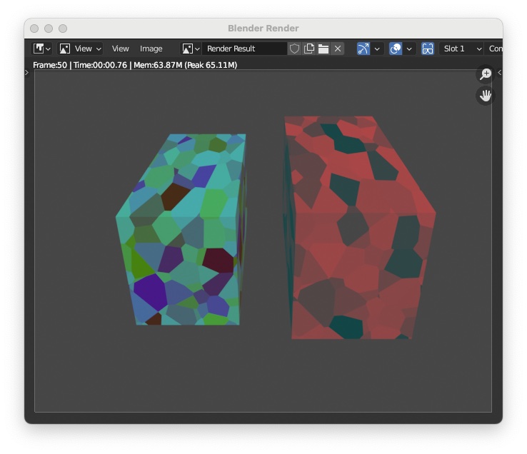
If you enter menu "Render > Render Image" you will see only the box seen by the color left camera. To be able to render color and depth, you need to enable "Stereoscopy". To this end:

  • Click on "Output Properties" icon (1)
  • And enable "Stereoscopy" (2)
    Now if you enter menu 
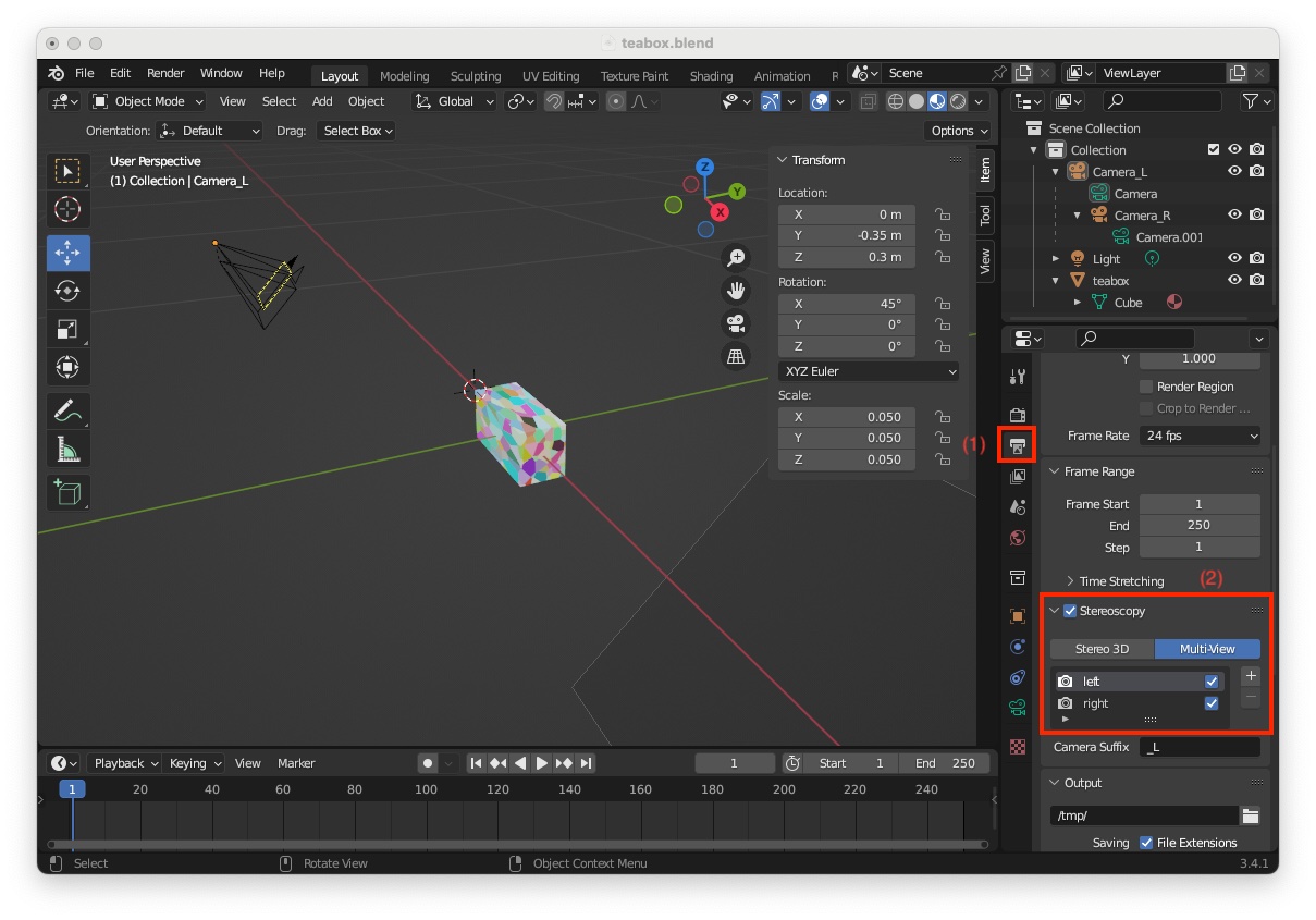
"Render > Render Image" you will see the box rendered by the left camera and right camera like the following image

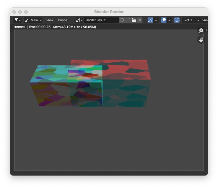
The last thing to do is to modify the project to generate the depth maps. To this end:

  • Select "View Layer Properties" icon (3)
  • And enable "Data > Z" (4)

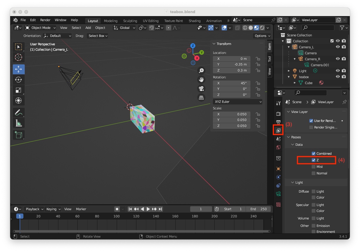
Now we need to set the format of the depth map images that will be rendered:

  • Switch to the "Compositor" screen layout, next to the menu bar (shortcut: Shift-F3)
  • Tick "Use Nodes" (5) and "Backdrop" (6)
  • Enter menu "Add > Output > File Output" to add file output node (7)
  • Add a link between the "Depth" output of the "Render Layers" node to the "File Output" node (8)
  • Modify "Base Path" to "/tmp/teabox/depth" the name of the folder that will host rendered depth maps (9)
  • Click on "Node" tab (10)
  • Change "File Format" to OpenEXR (11)

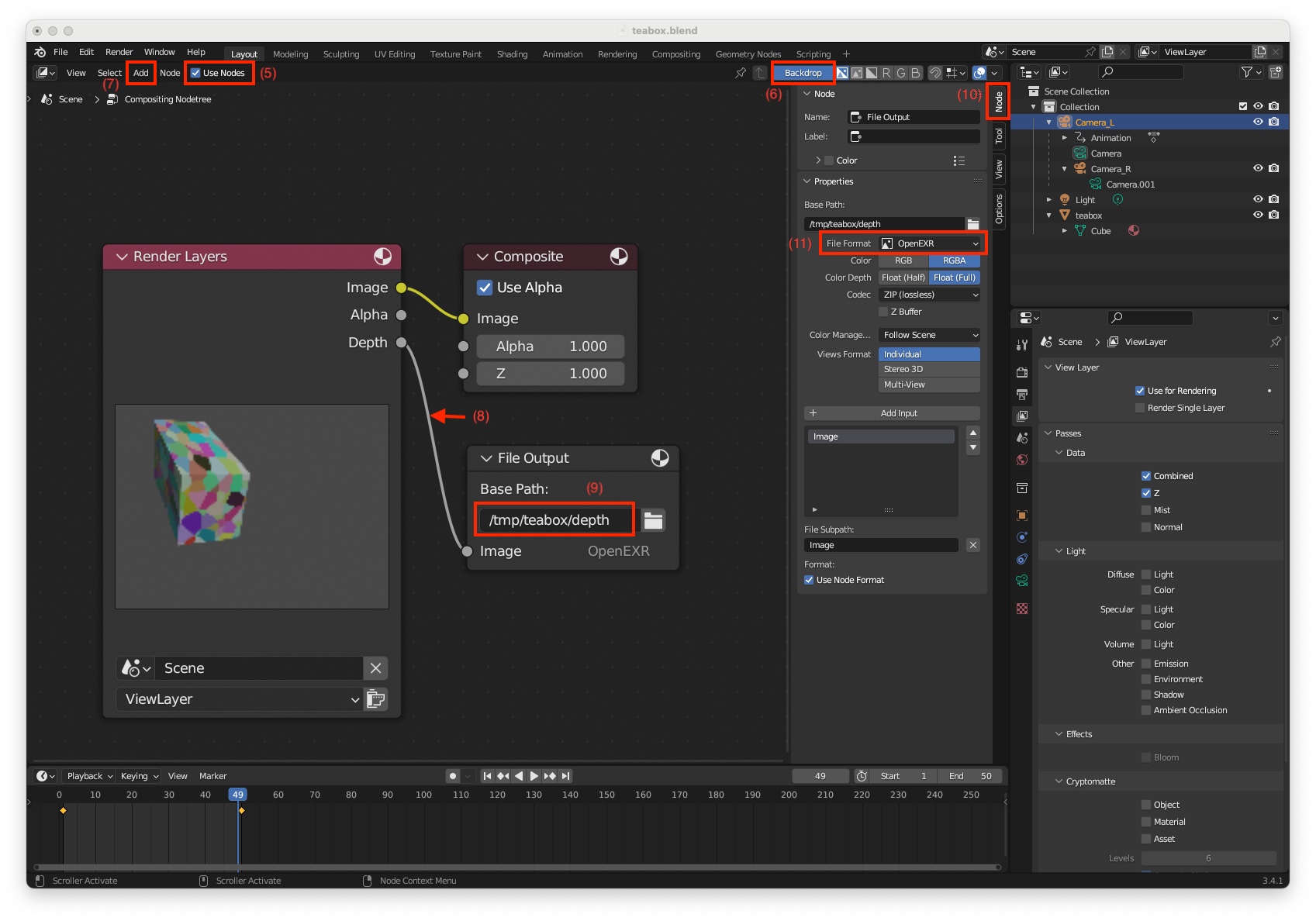
Now if you render an image using menu "Render > Render Image" in "/tmp/teabox/depth" folder you will get depth images for the left and right cameras. There is nos possibility to enable depth only for the right camera. Depth images corresponding to the left camera could be removed manually.

$ ls /tmp/teabox/depth
Image0001_L.exr Image0001_R.exr

Create a camera trajectory

We are now ready to animate the scene. First we have to define the camera initial position. This can be done easily:

  • Switch to "3D Vieport" (shortcut: Shift-F5)
  • Select "Camera_L" (1)
  • Using "Move" (2) and "Rotate" (3) tools move the stereo camera at a desired initial location / orientation. You can also enter the values directly in the "Transform" panel. A possible initial "Location" is X = 0.15, Y = -0.35, Z = 0.3 meters and "Rotation" X = 45, Y = 0, Z = 35 degrees (4)
  • Render the image entering menu "Render > Render Image" (5) to check if your object is visible in the image
  • If you are happy with your camera positionning, move the time slider to the "Start" frame number which is 1 (6)
  • Insert a keyframe with (shortcut: I) and choose "Location, Rotation & Scale" to insert a keyframe at the "Start" frame with number 1
  • A small yellow diamond should appear at frame 1 in the timeline (7)
  • If you render the image at the initial position you will get the following image

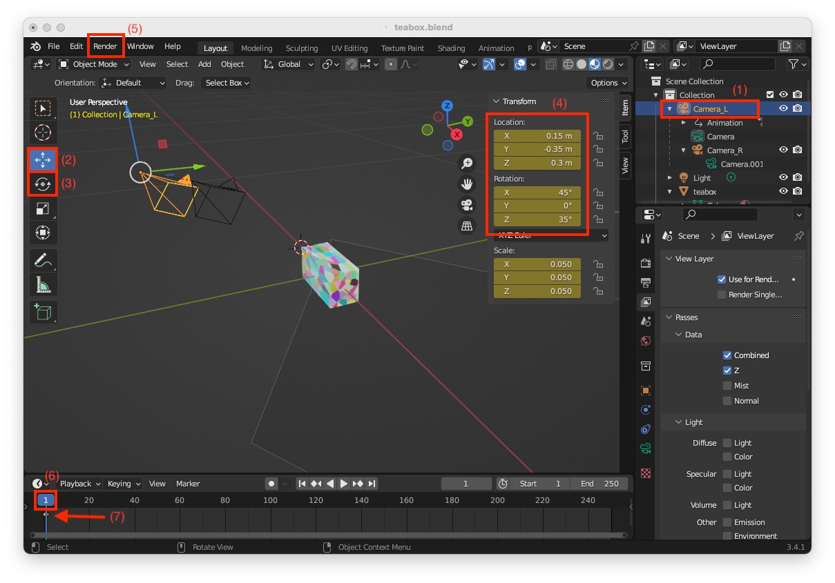
Now we have to perform the same operation for the camera final position.

  • If not already done, select "Camera_L" (8)
  • First you to have to define the "End" frame number of your animation. By default "End" frame is set to 250. Here we set this number to 50 (9)
  • Then move the time slider to the "End" frame number (10)
  • Now move the camera to the final position. Let us choose for final "Location" X = 0.3, Y = -0.15, Z = 0.15 meters and "Rotation" X = 60, Y = -10, Z = 65 degrees (11)
  • Render the image using menu "Render > Render Image" (12) to check if the box is visible in the image
  • Insert a keyframe with (shortcut: I) and choose "Location, Rotation & Scale" to insert a keyframe at the "End" frame with number 50
  • At this point, a small yellow diamond should appear at frame 50 in the timeline (13)
  • You can now play the animation pressing "Play Animation" button (14) and see the stereo pair moving from started position to end position
  • If you render the image at the final position you should see someting simitar to:

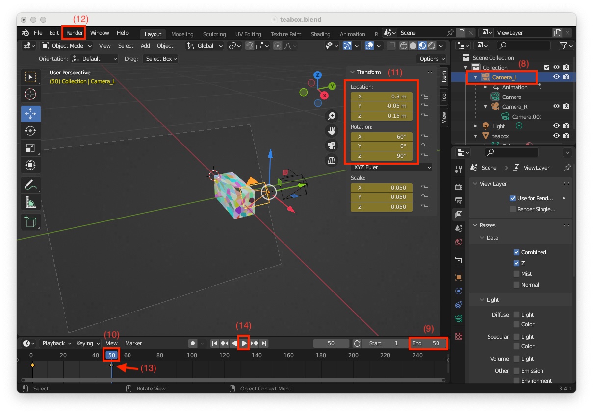
This completes the configuration of the scene in Blender. We strongly recommend that you save your project.

Note
The project used to create this tutorial is available in $VISP_WS/visp/tutorial/tracking/model-based/generic-rgbd-blender/data/teabox/blender/teabox.blend.

Generate full data

Here we want to run get_camera_pose_teabox.py Python script inside Blender to:

  • animate the RGB-D camera and retrieve in "/tmp/teabox" folder
  • color camera intrinsics in "Camera_L.xml"
  • depth camera intrinsics in "Camera_R.xml"
  • homogeneous transformation between depth and color camera in "depth_M_color.txt"
  • rendered color images in "color/%04d_L.jpg" files
  • rendered depth images in "depth/Images%04d_R.exr" files
  • ground truth in "ground-truth/Camera_L_%04d.txt" files

The Python script is available in "$VISP_WS/visp/tutorial/tracking/model-based/generic-rgbd-blender/" folder.

Since the script is displaying information using print() function, Blender should be started from a terminal.

  • On Ubuntu, simply open a terminal and launch
    $ blender
  • On MacOS, open a terminal and launch
    $ /Applications/Blender.app/Contents/MacOS/Blender

Then to run the Python script in Blender:

  • Switch from "3D Viewport" to "Text Editor" (shortcut: Shift-F11)
  • Open the Python script file $VISP_WS/visp/tutorial/tracking/model-based/generic-rgbd-blender/get_camera_pose_teabox.py
  • Click on "Run Script" (1) (shortcut: Alt-P)
  • In the terminal from which you launched Blender, you should see something similar to:
    Create /tmp/teabox/
    Create /tmp/teabox/camera_poses/
    Saved: /tmp/teabox/depth_M_color.txt
    Saved: /tmp/teabox/depth_M_color.txt
    Saved: /tmp/teabox/depth/Image0001_L.exr
    Saved: /tmp/teabox/depth/Image0001_R.exr
    Saved: '/tmp/teabox/color/0001_L.jpg'
    Saved: '/tmp/teabox/color/0001_R.jpg'
    Time: 00:00.29 (Saving: 00:00.00)
    Current Frame 1
    Saved: /tmp/teabox/camera_poses/Camera_L_001.txt
    Remove file: /tmp/teabox/color/0001_R.jpg
    Remove file: /tmp/teabox/depth/Image0001_L.exr
    Saved: /tmp/teabox/depth/Image0002_L.exr
    Saved: /tmp/teabox/depth/Image0002_R.exr
    Saved: '/tmp/teabox/color/0002_L.jpg'
    Saved: '/tmp/teabox/color/0002_R.jpg'
    Time: 00:00.22 (Saving: 00:00.00)
    ...

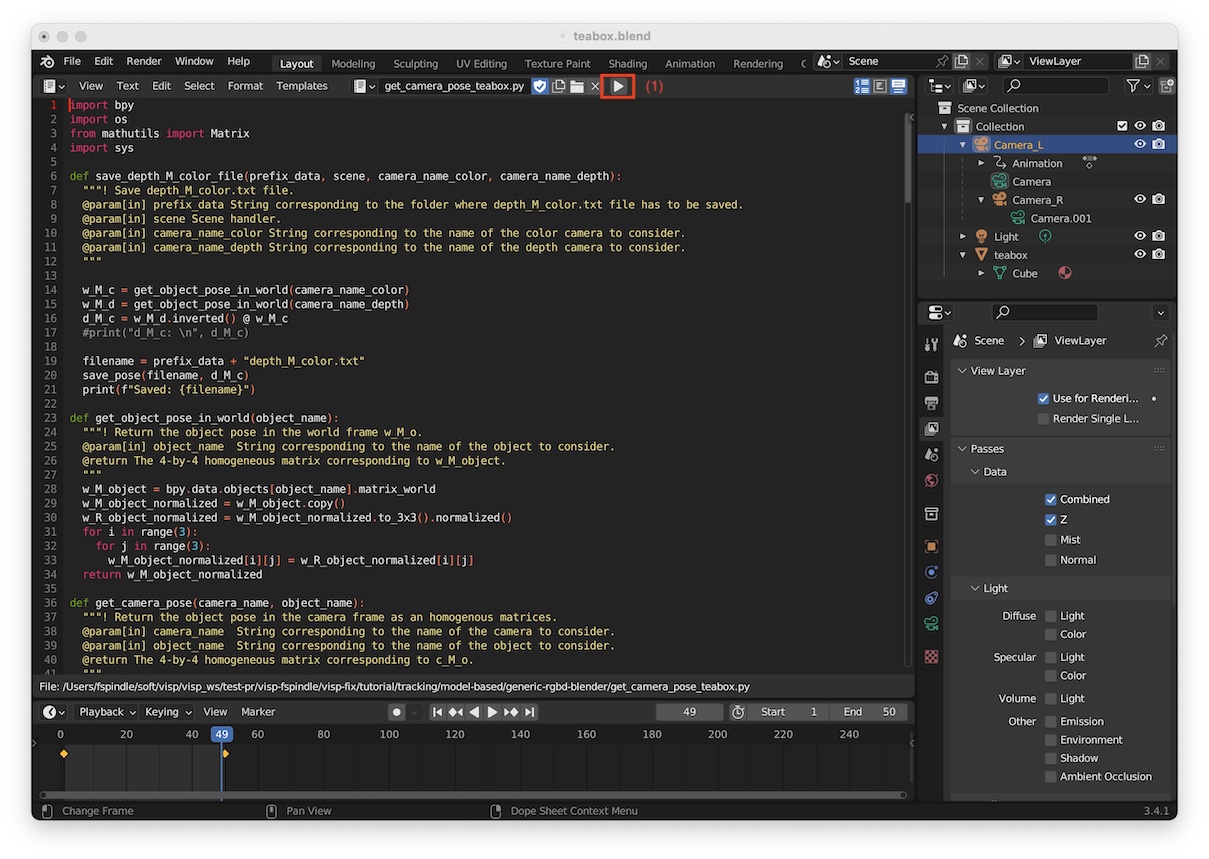
As explained previously, data are saved in the /tmp/teabox directory. By default, for each camera ("Camera_L" and "Camera_R") we render the color image and the depth image. The script will remove useless generated files by removing depth images corresponding to "Camera_L" and color images from "Camera_R".

How to get only camera intrinsics

If you are only interested to see which are the camera intrinsics of a given camera set in Blender, we provide get_camera_intrinsics.py Python script in $VISP_WS/visp/tutorial/tracking/model-based/generic-rgbd-blender/ folder.

As in the previous section, since this script is displaying information using print() function, Blender should be started from a terminal.

  • On Ubuntu, simply open a terminal and launch
    $ blender
  • On MacOS, open a terminal and launch
    $ /Applications/Blender.app/Contents/MacOS/Blender

Then to run this Python script in Blender:

  • Switch from "3D Viewport" to "Text Editor" (shortcut: Shift-F11)
  • Open the Python script file $VISP_WS/visp/tutorial/tracking/model-based/generic-rgbd-blender/get_camera_intrinsics.py
  • Verify that the camera name is set to "Camera_L"
    camera_name = "Camera_L"
  • Click on "Run Script" (shortcut: Alt-P)

In the terminal from which you launched Blender, you should get something similar to:

Intrinsics for Camera_L are K =
<Matrix 3x3 (700.0000, 0.0000, 320.0000)
( 0.0000, 700.0000, 240.0000)
( 0.0000, 0.0000, 1.0000)>
Note
The principal point is always in the middle of the image here.

You can retrieve the depth camera intrinsics using again get_camera_intrinsics.py just by modifying in the script the name of the camera

  • Modify the camera name to "Camera_R"
    camera_name = "Camera_R"
  • Click on Run Script (shortcut: Alt-P)

In the terminal from which you launched Blender, you should get something similar to:

Intrinsics for Camera_R are K =
<Matrix 3x3 (600.0000, 0.0000, 320.0000)
( 0.0000, 600.0000, 240.0000)
( 0.0000, 0.0000, 1.0000)>

Run model-based tracker on simulated data

Source code

The following C++ sample file also available in tutorial-mb-generic-tracker-rgbd-blender.cpp reads color and depth images, pointcloud is recreated using the depth camera intrinsic parameters. The ground truth data are read and printed along with the estimated camera pose by the model-based tracker. Since depth data are stored in OpenEXR file format, OpenCV is used for the reading.

#include <iostream>
#include <visp3/core/vpDisplay.h>
#include <visp3/core/vpIoTools.h>
#include <visp3/core/vpXmlParserCamera.h>
#include <visp3/gui/vpDisplayGDI.h>
#include <visp3/gui/vpDisplayOpenCV.h>
#include <visp3/gui/vpDisplayX.h>
#include <visp3/io/vpImageIo.h>
#include <visp3/mbt/vpMbGenericTracker.h>
#if defined(VISP_HAVE_OPENCV) && defined(HAVE_OPENCV_IMGCODECS) && defined(VISP_HAVE_PUGIXML)
namespace
{
bool read_data(unsigned int cpt, const std::string &video_color_images, const std::string &video_depth_images,
bool disable_depth, const std::string &video_ground_truth,
unsigned int &depth_width, unsigned int &depth_height,
std::vector<vpColVector> &pointcloud, const vpCameraParameters &cam_depth,
vpHomogeneousMatrix &cMo_ground_truth)
{
char buffer[FILENAME_MAX];
// Read color
snprintf(buffer, FILENAME_MAX, video_color_images.c_str(), cpt);
std::string filename_color = buffer;
if (!vpIoTools::checkFilename(filename_color)) {
std::cerr << "Cannot read: " << filename_color << std::endl;
return false;
}
vpImageIo::read(I, filename_color);
if (!disable_depth) {
// Read depth
snprintf(buffer, FILENAME_MAX, video_depth_images.c_str(), cpt);
std::string filename_depth = buffer;
if (!vpIoTools::checkFilename(filename_depth)) {
std::cerr << "Cannot read: " << filename_depth << std::endl;
return false;
}
cv::Mat depth_raw = cv::imread(filename_depth, cv::IMREAD_ANYDEPTH | cv::IMREAD_ANYCOLOR);
if (depth_raw.empty()) {
std::cerr << "Cannot read: " << filename_depth << std::endl;
return false;
}
depth_width = static_cast<unsigned int>(depth_raw.cols);
depth_height = static_cast<unsigned int>(depth_raw.rows);
I_depth_raw.resize(depth_height, depth_width);
pointcloud.resize(depth_width * depth_height);
for (int i = 0; i < depth_raw.rows; i++) {
for (int j = 0; j < depth_raw.cols; j++) {
I_depth_raw[i][j] = static_cast<uint16_t>(32767.5f * depth_raw.at<cv::Vec3f>(i, j)[0]);
double x = 0.0, y = 0.0;
// Manually limit the field of view of the depth camera
double Z = depth_raw.at<cv::Vec3f>(i, j)[0] > 2.0f ? 0.0 : static_cast<double>(depth_raw.at<cv::Vec3f>(i, j)[0]);
vpPixelMeterConversion::convertPoint(cam_depth, j, i, x, y);
size_t idx = static_cast<size_t>(i * depth_raw.cols + j);
pointcloud[idx].resize(3);
pointcloud[idx][0] = x * Z;
pointcloud[idx][1] = y * Z;
pointcloud[idx][2] = Z;
}
}
}
// Read ground truth
snprintf(buffer, FILENAME_MAX, video_ground_truth.c_str(), cpt);
std::string filename_pose = buffer;
cMo_ground_truth.load(filename_pose);
return true;
}
} // namespace
void usage(const char **argv, int error, const std::string &data_path, const std::string &model_path, int first_frame)
{
std::cout << "Synopsis" << std::endl
<< " " << argv[0]
<< " [--data-path <path>] [--model-path <path>] [--first-frame <index>] [--disable-depth] "
<< " [--disable-klt] [--step-by-step] [--display-ground-truth] [--help, -h]" << std::endl
<< std::endl;
std::cout << "Description" << std::endl
<< " --data-path <path> Path to the data generated by Blender get_camera_pose_teabox.py" << std::endl
<< " Python script."
<< " Default: " << data_path << std::endl
<< std::endl
<< " --model-path <path> Path to the cad model and tracker settings." << std::endl
<< " Default: " << model_path << std::endl
<< std::endl
<< " --first-frame <index> First frame number to process." << std::endl
<< " Default: " << first_frame << std::endl
<< std::endl
<< " --disable-depth Flag to turn off tracker depth features." << std::endl
<< std::endl
<< " --disable-klt Flag to turn off tracker keypoints features." << std::endl
<< std::endl
<< " --step-by-step Flag to enable step by step mode." << std::endl
<< std::endl
<< " --display-ground-truth Flag to enable displaying ground truth." << std::endl
<< " When this flag is enabled, there is no tracking. This flag is useful" << std::endl
<< " to validate the ground truth over the rendered images." << std::endl
<< std::endl
<< " --help, -h Print this helper message." << std::endl
<< std::endl;
if (error) {
std::cout << "Error" << std::endl
<< " "
<< "Unsupported parameter " << argv[error] << std::endl;
}
}
int main(int argc, const char **argv)
{
std::string opt_data_path = "data/teabox";
std::string opt_model_path = "model/teabox";
unsigned int opt_first_frame = 1;
bool opt_disable_depth = false;
bool opt_disable_klt = false;
bool opt_display_ground_truth = false;
bool opt_step_by_step = false;
for (int i = 1; i < argc; i++) {
if (std::string(argv[i]) == "--data-path" && i + 1 < argc) {
opt_data_path = std::string(argv[i + 1]);
i++;
}
else if (std::string(argv[i]) == "--model-path" && i + 1 < argc) {
opt_model_path = std::string(argv[i + 1]);
i++;
}
else if (std::string(argv[i]) == "--disable-depth") {
opt_disable_depth = true;
}
else if (std::string(argv[i]) == "--disable-klt") {
opt_disable_klt = true;
}
else if (std::string(argv[i]) == "--display-ground-truth") {
opt_display_ground_truth = true;
}
else if (std::string(argv[i]) == "--step-by-step") {
opt_step_by_step = true;
}
else if (std::string(argv[i]) == "--first-frame" && i + 1 < argc) {
opt_first_frame = static_cast<unsigned int>(atoi(argv[i + 1]));
i++;
}
else if (std::string(argv[i]) == "--help" || std::string(argv[i]) == "-h") {
usage(argv, 0, opt_data_path, opt_model_path, opt_first_frame);
return EXIT_SUCCESS;
}
else {
usage(argv, i, opt_data_path, opt_model_path, opt_first_frame);
return EXIT_FAILURE;
}
}
std::string video_color_images = vpIoTools::createFilePath(opt_data_path, "color/%04d_L.jpg");
std::string video_depth_images = vpIoTools::createFilePath(opt_data_path, "depth/Image%04d_R.exr");
std::string ground_truth = vpIoTools::createFilePath(opt_data_path, "ground-truth/Camera_L_%04d.txt");
std::string extrinsic_file = vpIoTools::createFilePath(opt_data_path, "depth_M_color.txt");
std::string color_camera_name = "Camera_L";
std::string depth_camera_name = "Camera_R";
std::string color_intrinsic_file = vpIoTools::createFilePath(opt_data_path, color_camera_name + ".xml");
std::string depth_intrinsic_file = vpIoTools::createFilePath(opt_data_path, depth_camera_name + ".xml");
std::string mbt_config_color = vpIoTools::createFilePath(opt_model_path, "teabox_color.xml");
std::string mbt_config_depth = vpIoTools::createFilePath(opt_model_path, "teabox_depth.xml");
std::string mbt_cad_model = vpIoTools::createFilePath(opt_model_path, "teabox.cao");
std::string mbt_init_file = vpIoTools::createFilePath(opt_model_path, "teabox.init");
std::cout << "Input data" << std::endl;
std::cout << " Color images : " << video_color_images << std::endl;
std::cout << " Depth images : " << (opt_disable_depth ? "Disabled" : video_depth_images) << std::endl;
std::cout << " Extrinsics : " << (opt_disable_depth ? "Disabled" : extrinsic_file) << std::endl;
std::cout << " Color intrinsics: " << color_intrinsic_file << std::endl;
std::cout << " Depth intrinsics: " << (opt_disable_depth ? "Disabled" : depth_intrinsic_file) << std::endl;
std::cout << " Ground truth : " << ground_truth << std::endl;
std::cout << "Tracker settings" << std::endl;
std::cout << " Color config : " << mbt_config_color << std::endl;
std::cout << " Depth config : " << mbt_config_depth << std::endl;
std::cout << " CAD model : " << mbt_cad_model << std::endl;
std::cout << " First frame : " << opt_first_frame << std::endl;
std::cout << " Step by step : " << opt_step_by_step << std::endl;
if (opt_display_ground_truth) {
std::cout << " Ground truth is used to project the cad model (no tracking)" << std::endl;
}
else {
std::cout << " Init file : " << mbt_init_file << std::endl;
std::cout << " Features : moving-edges " << (opt_disable_klt ? "" : "+ keypoints") << (opt_disable_depth ? "" : " + depth") << std::endl;
}
std::vector<int> tracker_types;
if (opt_disable_klt) {
tracker_types.push_back(vpMbGenericTracker::EDGE_TRACKER);
}
else {
#if defined(VISP_HAVE_OPENCV) && defined(HAVE_OPENCV_IMGPROC) && defined(HAVE_OPENCV_VIDEO)
#else
std::cout << "Warning: keypoints cannot be used as features since ViSP is not build with OpenCV 3rd party" << std::endl;
#endif
}
if (!opt_disable_depth)
tracker_types.push_back(vpMbGenericTracker::DEPTH_DENSE_TRACKER);
vpMbGenericTracker tracker(tracker_types);
if (!opt_disable_depth)
tracker.loadConfigFile(mbt_config_color, mbt_config_depth);
else
tracker.loadConfigFile(mbt_config_color);
tracker.loadModel(mbt_cad_model);
vpCameraParameters cam_color, cam_depth;
// Update intrinsics camera parameters from Blender generated data
if (p.parse(cam_color, color_intrinsic_file, color_camera_name, vpCameraParameters::perspectiveProjWithoutDistortion)
std::cout << "Cannot found intrinsics for camera " << color_camera_name << std::endl;
}
if (p.parse(cam_depth, depth_intrinsic_file, depth_camera_name, vpCameraParameters::perspectiveProjWithoutDistortion)
std::cout << "Cannot found intrinsics for camera " << depth_camera_name << std::endl;
}
if (!opt_disable_depth)
tracker.setCameraParameters(cam_color, cam_depth);
else
tracker.setCameraParameters(cam_color);
// Reload intrinsics from tracker (useless)
if (!opt_disable_depth)
tracker.getCameraParameters(cam_color, cam_depth);
else
tracker.getCameraParameters(cam_color);
tracker.setDisplayFeatures(true);
std::cout << "cam_color:\n" << cam_color << std::endl;
if (!opt_disable_depth)
std::cout << "cam_depth:\n" << cam_depth << std::endl;
vpImage<uint16_t> I_depth_raw;
unsigned int depth_width = 0, depth_height = 0;
std::vector<vpColVector> pointcloud;
vpHomogeneousMatrix cMo_ground_truth;
unsigned int frame_cpt = opt_first_frame;
read_data(frame_cpt, video_color_images, video_depth_images, opt_disable_depth, ground_truth,
I, I_depth_raw, depth_width, depth_height, pointcloud, cam_depth, cMo_ground_truth);
vpImageConvert::createDepthHistogram(I_depth_raw, I_depth);
#if defined(VISP_HAVE_X11)
vpDisplayX d1, d2;
#elif defined(VISP_HAVE_GDI)
vpDisplayGDI d1, d2;
#elif defined (HAVE_OPENCV_HIGHGUI)
#endif
d1.init(I, 0, 0, "Color image");
if (!opt_disable_depth) {
d2.init(I_depth, static_cast<int>(I.getWidth()), 0, "Depth image");
}
vpHomogeneousMatrix depth_M_color;
if (!opt_disable_depth) {
depth_M_color.load(extrinsic_file);
tracker.setCameraTransformationMatrix("Camera2", depth_M_color);
std::cout << "depth_M_color:\n" << depth_M_color << std::endl;
}
if (opt_display_ground_truth) {
tracker.initFromPose(I, cMo_ground_truth); // I and I_depth must be the same size when using depth features!
}
else {
tracker.initClick(I, mbt_init_file, true); // I and I_depth must be the same size when using depth features!
}
try {
bool quit = false;
while (!quit && read_data(frame_cpt, video_color_images, video_depth_images, opt_disable_depth,
ground_truth, I, I_depth_raw, depth_width, depth_height, pointcloud, cam_depth,
cMo_ground_truth)) {
vpImageConvert::createDepthHistogram(I_depth_raw, I_depth);
if (opt_display_ground_truth) {
tracker.initFromPose(I, cMo_ground_truth); // I and I_depth must be the same size when using depth features!
}
else {
if (!opt_disable_depth) {
std::map<std::string, const vpImage<unsigned char> *> mapOfImages;
std::map<std::string, const std::vector<vpColVector> *> mapOfPointClouds;
std::map<std::string, unsigned int> mapOfPointCloudWidths;
std::map<std::string, unsigned int> mapOfPointCloudHeights;
mapOfImages["Camera1"] = &I;
mapOfPointClouds["Camera2"] = &pointcloud;
mapOfPointCloudWidths["Camera2"] = depth_width;
mapOfPointCloudHeights["Camera2"] = depth_height;
tracker.track(mapOfImages, mapOfPointClouds, mapOfPointCloudWidths, mapOfPointCloudHeights);
}
else {
tracker.track(I);
}
}
vpHomogeneousMatrix cMo = tracker.getPose();
std::cout << "\nFrame: " << frame_cpt << std::endl;
if (!opt_display_ground_truth)
std::cout << "cMo:\n" << cMo << std::endl;
std::cout << "cMo ground truth:\n" << cMo_ground_truth << std::endl;
if (!opt_disable_depth) {
tracker.display(I, I_depth, cMo, depth_M_color * cMo, cam_color, cam_depth, vpColor::red, 2);
vpDisplay::displayFrame(I_depth, depth_M_color * cMo, cam_depth, 0.05, vpColor::none, 2);
}
else {
tracker.display(I, cMo, cam_color, vpColor::red, 2);
}
vpDisplay::displayFrame(I, cMo, cam_color, 0.05, vpColor::none, 2);
std::ostringstream oss;
oss << "Frame: " << frame_cpt;
vpDisplay::setTitle(I, oss.str());
if (opt_step_by_step) {
vpDisplay::displayText(I, 20, 10, "Left click to trigger next step", vpColor::red);
vpDisplay::displayText(I, 40, 10, "Right click to quit step-by-step mode", vpColor::red);
}
else {
vpDisplay::displayText(I, 20, 10, "Left click to trigger step-by-step mode", vpColor::red);
vpDisplay::displayText(I, 40, 10, "Right click to exit...", vpColor::red);
}
if (!opt_display_ground_truth) {
{
std::stringstream ss;
ss << "Nb features: " << tracker.getError().size();
vpDisplay::displayText(I, I.getHeight() - 50, 20, ss.str(), vpColor::red);
}
{
std::stringstream ss;
ss << "Features: edges " << tracker.getNbFeaturesEdge() << ", klt " << tracker.getNbFeaturesKlt()
<< ", depth " << tracker.getNbFeaturesDepthDense();
vpDisplay::displayText(I, I.getHeight() - 30, 20, ss.str(), vpColor::red);
}
}
vpDisplay::flush(I_depth);
// Button 1: start step by step if not enabled from command line option
// Button 2: enables step by step mode
// Button 3: ends step by step mode if enabled
// quit otherwise
if (vpDisplay::getClick(I, button, opt_step_by_step)) {
if (button == vpMouseButton::button1 && opt_step_by_step == false) {
opt_step_by_step = true;
}
else if (button == vpMouseButton::button3 && opt_step_by_step == true) {
opt_step_by_step = false;
}
else if (button == vpMouseButton::button3 && opt_step_by_step == false) {
quit = true;
}
else if (button == vpMouseButton::button2) {
opt_step_by_step = true;
}
}
frame_cpt++;
}
}
catch (std::exception &e) {
std::cerr << "Catch exception: " << e.what() << std::endl;
}
return EXIT_SUCCESS;
}
#else
int main()
{
std::cout << "To run this tutorial, ViSP should be built with OpenCV and pugixml libraries." << std::endl;
return EXIT_SUCCESS;
}
#endif
Generic class defining intrinsic camera parameters.
@ perspectiveProjWithoutDistortion
Perspective projection without distortion model.
static const vpColor red
Definition: vpColor.h:211
static const vpColor none
Definition: vpColor.h:223
Display for windows using GDI (available on any windows 32 platform).
Definition: vpDisplayGDI.h:128
The vpDisplayOpenCV allows to display image using the OpenCV library. Thus to enable this class OpenC...
Use the X11 console to display images on unix-like OS. Thus to enable this class X11 should be instal...
Definition: vpDisplayX.h:128
void init(vpImage< unsigned char > &I, int win_x=-1, int win_y=-1, const std::string &win_title="") vp_override
static bool getClick(const vpImage< unsigned char > &I, bool blocking=true)
static void display(const vpImage< unsigned char > &I)
static void displayFrame(const vpImage< unsigned char > &I, const vpHomogeneousMatrix &cMo, const vpCameraParameters &cam, double size, const vpColor &color=vpColor::none, unsigned int thickness=1, const vpImagePoint &offset=vpImagePoint(0, 0), const std::string &frameName="", const vpColor &textColor=vpColor::black, const vpImagePoint &textOffset=vpImagePoint(15, 15))
static void setTitle(const vpImage< unsigned char > &I, const std::string &windowtitle)
static void flush(const vpImage< unsigned char > &I)
static void displayText(const vpImage< unsigned char > &I, const vpImagePoint &ip, const std::string &s, const vpColor &color)
Implementation of an homogeneous matrix and operations on such kind of matrices.
void load(std::ifstream &f)
static void createDepthHistogram(const vpImage< uint16_t > &src_depth, vpImage< vpRGBa > &dest_rgba)
static void read(vpImage< unsigned char > &I, const std::string &filename, int backend=IO_DEFAULT_BACKEND)
Definition: vpImageIo.cpp:143
unsigned int getWidth() const
Definition: vpImage.h:245
void resize(unsigned int h, unsigned int w)
resize the image : Image initialization
Definition: vpImage.h:783
unsigned int getHeight() const
Definition: vpImage.h:184
static bool checkFilename(const std::string &filename)
Definition: vpIoTools.cpp:1199
static std::string createFilePath(const std::string &parent, const std::string &child)
Definition: vpIoTools.cpp:2142
Real-time 6D object pose tracking using its CAD model.
static void convertPoint(const vpCameraParameters &cam, const double &u, const double &v, double &x, double &y)
XML parser to load and save intrinsic camera parameters.
vpCameraParameters getCameraParameters() const
int parse(vpCameraParameters &cam, const std::string &filename, const std::string &camera_name, const vpCameraParameters::vpCameraParametersProjType &projModel, unsigned int image_width=0, unsigned int image_height=0, bool verbose=true)
Note
Here the depth values are manually clipped in order to simulate the depth range of a depth sensor. This probably can be done directly in Blender.

Usage on simulated data

Once build, to get tutorial-mb-generic-tracker-rgbd-blender.cpp usage, just run:

$ cd $VISP_WS/visp-build/tutorial/tracking/model-based/generic-rgbd-blender
$ ./tutorial-mb-generic-tracker-rgbd-blender -h
Synopsis
./tutorial-mb-generic-tracker-rgbd-blender [--data-path <path>] [--model-path <path>]
[--first-frame <index>] [--disable-depth] [--disable-klt] [--step-by-step]
[--display-ground-truth] [--help, -h]
Description
--data-path <path> Path to the data generated by Blender get_camera_pose_teabox.py
Python script. Default: data/teabox
--model-path <path> Path to the cad model and tracker settings.
Default: model/teabox
--first-frame <index> First frame number to process.
Default: 1
--disable-depth Flag to turn off tracker depth features.
--disable-klt Flag to turn off tracker keypoints features.
--step-by-step Flag to enable step by step mode.
--display-ground-truth Flag to enable displaying ground truth.
When this flag is enabled, there is no tracking. This flag is useful
to validate the ground truth over the rendered images.
--help, -h Print this helper message.

Default parameters allow to run the binary with the data provided in ViSP. Just run:

$ ./tutorial-mb-generic-tracker-rgbd-blender

To run the binary on the data generated by Blender in "/tmp/teabox" folder, just run:

$ ./tutorial-mb-generic-tracker-rgbd-blender --data-path /tmp/teabox

You should be able to see similar tracking results as the one given in the next video.

Note
If you just want to project the cad model in the images using the ground truth, without tracking, you may run:
$ ./tutorial-mb-generic-tracker-rgbd-blender --data-path /tmp/teabox --display-ground-truth

Next tutorial

You are now ready to see the next Tutorial: Template tracking.