|
Visual Servoing Platform
version 3.6.1 under development (2025-02-06)
|
|
Visual Servoing Platform
version 3.6.1 under development (2025-02-06)
|
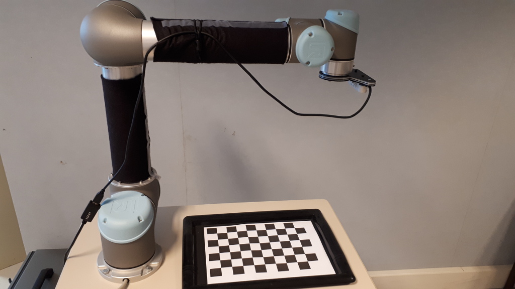
This tutorial focuses estimation of the homogeneous transformation between the robot end-effector and the camera frame. As a use case, we will consider in this tutorial the case of either:
The principle of the extrinsic calibration is easy to apply to any other robot equipped with any other camera attached to the robot end-effector.
Let us consider:
 the homogeneous transformation between the robot base frame (also called fixed frame) and the robot end-effector
 the homogeneous transformation between the camera frame and a calibration grid frame (also called object frame), typically the OpenCV chessboard
 the homogeneous transformation between the end-effector and the camera frame. This is the transformation corresponding to the extrinsic eye-in-hand transformation that we have to estimate.
The calibration process described in this tutorial consists in 3 steps:
poses, images of the chessboard and camera intrinsic parameters pose of the chessboard from the images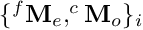 corresponding to couple of poses
  the last step is to estimate the transformation.
Note that all the material (source code) described in this tutorial is part of ViSP source code (in apps/calibration folder) and could be found in https://github.com/lagadic/visp/tree/master/apps/calibration.
To get good calibration results follow these Recommendations.
In order to compute the pose from the chessboard image, there is the need to get the camera intrinsic parameters. Depending on the device, these parameters are part of the device SDK or firmware. This is for example the case for our Intel Realsense D435 camera considered in this tutorial. These intrinsic parameters could be retrieved using vpRealSense2::getCameraParameters().
If you have an other camera, or if you want to have a better estimation than the factory parameters you may follow Tutorial: Camera intrinsic calibration. Otherwise you can skip this section.
Download and print a black and white chessboard OpenCV_Chessboard.pdf.
Glue the chessboard on a flat surface and put it under the camera.
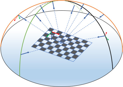
The objective here is to complete step 1 by acquiring couples of poses and the corresponding images of the chessboard. To this end move the camera attached to the robot to different positions. At least 8 to 10 positions are requested. To define a good position you have to imagine a half sphere over the chessboard and select positions that discretise as much as possible all the half sphere surface. For each position you should see all the chessboard as large as possible in the image.
The following image shows a set of 10 camera positions covering the half sphere over the chessboard. Each blue arrow represents camera z-axis pointing to a region close to the chessboard center. The orientation of the frame attached to the chessboard doesn't matter. The chessboard z-axis could be going upward or not.
To acquire images of the chessboard, depending of your device you can follow Tutorial: Image frame grabbing. Images could be saved in jpeg or png format, or any format supported by ViSP.
To get the corresponding poses, you need to use one of our robot interface like vpRobotFranka::get_fMe(), vpRobotUniversalRobots::get_fMe()... It returns the homogeneous transformation between the robot base frame and the robot end-effector. The following code snippet shows how to save the pose in yaml format:
To complete this step, you need also to get or calibrate your camera in order to obtain its intrinsic parameters. Camera intrinsic parameters need to be saved in an xml file. If you have an Intel RealSense device you can directly get the parameters using vpRealSense2::getCameraParameters() and then save the parameters in an xml file using vpXmlParserCamera::save(). An example is given in visp-acquire-franka-calib-data.cpp or in visp-acquire-universal-robots-calib-data.cpp
As an example, in ViSP source code you will find a dataset corresponding to data acquired with a real robot:
$ cd $VISP_WS/visp-build/apps/calibration
$ ls *.{xml,png,yaml}
camera.xml   image-3.png  image-6.png  pose_fPe_1.yaml  pose_fPe_4.yaml  pose_fPe_7.yaml
image-1.png  image-4.png  image-7.png  pose_fPe_2.yaml  pose_fPe_5.yaml  pose_fPe_8.yaml
image-2.png  image-5.png  image-8.png  pose_fPe_3.yaml  pose_fPe_6.yaml
In this dataset, you will find 8 pairs of images and their corresponding robot end-effector poses, and also the camera parameters in camera.xml file. Each squareor the calibration grid is 0.0262 m large.
Here we will complete step 2 by computing for each image the corresponding pose of the chessboard using the camera intrinsic parameters recorded in the xml file.
To this end you can use visp-compute-chessboard-poses binary to compute the different poses of the chessboard with respect to the camera frame.
Considering the dataset presented in step 1, and knowing that the size of the each chessboard square is 0.0262 by 0.0262 meter (modify option --square-size according to your chessboard), to proceed with the dataset you may run:
$ ./visp-compute-chessboard-poses --square-size 0.0262 --input image-%d.png --intrinsic camera.xml --output pose_cPo_%d.yaml
It produces as output the corresponding poses pose-cMo-<number>.yaml.
$ ./visp-compute-chessboard-poses --square-size 0.0262 --input image-%d.png --intrinsic camera.xml --output pose_cPo_%d.yaml
Parameters:
  chessboard width             : 9
  chessboard height            : 6
  chessboard square size [m]   : 0.0262
  input images location        : image-%d.png
  camera param file name [.xml]: camera.xml
  camera name                  : Camera
  output camera poses          : pose_cPo_%d.yaml

Found camera with name: "Camera"
Camera parameters used to compute the pose:
Camera parameters for perspective projection with distortion:
  px = 605.1467285   py = 604.7915039
  u0 = 325.5325317   v0 = 244.9508362
  kud = -0
  kdu = 0

Save pose_cPo_1.yaml
Save pose_cPo_2.yaml
Save pose_cPo_3.yaml
Save pose_cPo_4.yaml
Save pose_cPo_5.yaml
Save pose_cPo_6.yaml
Save pose_cPo_7.yaml
Save pose_cPo_8.yaml
The source code corresponding to the binary is available in visp-compute-chessboard-poses.cpp.
The final step 3 consists now to estimate the transformation from the couples of and poses.
Complete the calibration running visp-compute-hand-eye-calibration binary. It will get the data from the pair of files, pose_fPe_%d.yaml and pose_cPo_%d.yaml located in ./ folder.
$ ./visp-compute-hand-eye-calibration --data-path . --fPe pose_fPe_%d.yaml --cPo pose_cPo_%d.yaml --output eMc.yaml
It produces as output the end-effector to camera frame transformation in eMc.yaml and eMc.txt files.
$ ./visp-compute-hand-eye-calibration --data-path . --fPe pose_fPe_%d.yaml --cPo pose_cPo_%d.yaml --output eMc.yaml
Use data from ./pose_fPe_1.yaml and from ./pose_cPo_1.yaml
Use data from ./pose_fPe_2.yaml and from ./pose_cPo_2.yaml
Use data from ./pose_fPe_3.yaml and from ./pose_cPo_3.yaml
Use data from ./pose_fPe_4.yaml and from ./pose_cPo_4.yaml
Use data from ./pose_fPe_5.yaml and from ./pose_cPo_5.yaml
Use data from ./pose_fPe_6.yaml and from ./pose_cPo_6.yaml
Use data from ./pose_fPe_7.yaml and from ./pose_cPo_7.yaml
Use data from ./pose_fPe_8.yaml and from ./pose_cPo_8.yaml

Rotation and translation after VVS
Distance theta between rMo(0) and mean (deg) = 0.576558
Distance theta between rMo(1) and mean (deg) = 0.23848
Distance theta between rMo(2) and mean (deg) = 1.32688
Distance theta between rMo(3) and mean (deg) = 0.346355
Distance theta between rMo(4) and mean (deg) = 0.17516
Distance theta between rMo(5) and mean (deg) = 0.179329
Distance theta between rMo(6) and mean (deg) = 0.29173
Distance theta between rMo(7) and mean (deg) = 0.656298
Mean residual rMo(8) - rotation (deg) = 0.596712
Distance d between rMo(0) and mean (m) = 0.00121958
Distance d between rMo(1) and mean (m) = 0.000620416
Distance d between rMo(2) and mean (m) = 0.00185042
Distance d between rMo(3) and mean (m) = 0.000976499
Distance d between rMo(4) and mean (m) = 0.00076708
Distance d between rMo(5) and mean (m) = 0.000776703
Distance d between rMo(6) and mean (m) = 0.000815081
Distance d between rMo(7) and mean (m) = 0.00156322
Mean residual rMo(8) - translation (m) = 0.00114835
Mean residual rMo(8) - global = 0.00740886

** Hand-eye calibration succeed

** Hand-eye (eMc) transformation estimated:
0.9997661247  -0.02056658567  0.006686659472  -0.03609519439
0.02054910044  0.9997852711  0.002673221616  -0.05872368236
-0.006740202695  -0.002535191578  0.9999740709  0.03030957892
0  0  0  1
** Corresponding pose vector: -0.03609519439  -0.05872368236  0.03030957892  -0.00260441258  0.006713962092  0.02055946911

** Translation [m]: -0.03609519439 -0.05872368236 0.03030957892
** Rotation (theta-u representation) [rad]: -0.00260441258  0.006713962092  0.02055946911
** Rotation (theta-u representation) [deg]: -0.149221849 0.3846816917 1.177970809
** Rotation (quaternion representation) [rad]: -0.001302180542  0.003356914669  0.01027953129  0.9999406816

Save transformation matrix eMc as a vpPoseVector in eMc.yaml
The result of the calibration is available in eMc.yaml file that contains the as a vpPoseVector pose vector, with translation in meter and rotation as a  vector with values in radians.
$ more eMc.yaml
rows: 6
cols: 1
data:
  - [-0.0360952]
  - [-0.0587237]
  - [0.0303096]
  - [-0.00260441]
  - [0.00671396]
  - [0.0205595]
You can also see the corresponding homogeneous transformation:
$ more eMc.yaml
$ more eMc.txt
0.9997661247  -0.02056658567  0.006686659472  -0.03609519439
0.02054910044  0.9997852711  0.002673221616  -0.05872368236
-0.006740202695  -0.002535191578  0.9999740709  0.03030957892
0  0  0  1
The source code corresponding to the binary is available in visp-compute-hand-eye-calibration.cpp.
Since ViSP 3.3.1 we provide hand_eye_calibration_show_extrinsics.py python script that allows to display camera poses used to acquire data. Prior to use that script, you need to install scipy and pyyaml:
$ sudo apt install python-pip
$ pip install scipy pyyaml matplotlib
To visualize camera poses:
$ python hand_eye_calibration_show_extrinsics.py --ndata 8 --eMc_yaml eMc.yaml
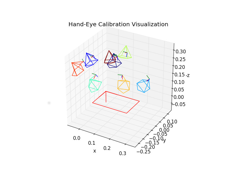
We recall, that a good hand-eye calibration is obtained when the camera poses are covering the surface of a half sphere over the grid.
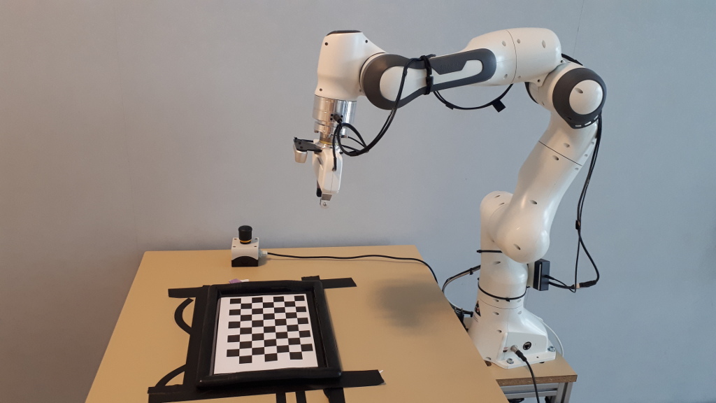
In this section we suppose that you have a Panda robot from Franka Emika with a Realsense camera attached to its end-effector.
If not already done, follow Configure Ethernet and Connect to Franka desk instructions to power on the Panda robot. Then if this is not already done, follow Install Franka library and Configure and build ViSP.
If not already done, you need also to install librealsense 2.x 3rd party and build ViSP to enable vpRealSense2 class usage.
Step 1: Acquire robot poses and images
Connect the Realsense D435 camera to the computer, put the chessboard in the camera field of view, enter in apps/calibration folder and run visp-acquire-franka-calib-data binary to acquire the images and the corresponding robot end-effector positions:
$ cd apps/calibration
$ ./visp-acquire-franka-calib-data
By default the robot controller IP is 192.168.1.1. If your Franka has an other IP (let say 10.0.0.2) use --ip option like:
$ ./visp-acquire-franka-calib-data --ip 10.0.0.2
Click with the left mouse button to acquire data. It records the following outputs:
franka_camera.xml : XML file that contains the intrinsic camera parameters extracted from camera firmwarefranka_image-<number>.png + franka_pose_fMe-<number>.txt with number starting from 1. franka_pose_fMe-<number>.yaml is the pose of the end-effector expressed in the robot base frame , while franka_image-<number>.png is the image captured at the corresponding robot position.Move the robot to an other position such as the chessboard remains in the image and repeat data acquisition by a left mouse click. We recommend to acquire data at 8 to 10 different robot positions.
A right mouse click ends this step exiting the binary.
This is the output when 8 different positions are considered:
$ ./visp-acquire-franka-calib-data
Image size: 640 x 480
Found camera with name: "Camera"
Save: franka_image-1.png and franka_pose_fPe_1.yaml
Save: franka_image-2.png and franka_pose_fPe_2.yaml
Save: franka_image-3.png and franka_pose_fPe_3.yaml
Save: franka_image-4.png and franka_pose_fPe_4.yaml
Save: franka_image-5.png and franka_pose_fPe_5.yaml
Save: franka_image-6.png and franka_pose_fPe_6.yaml
Save: franka_image-7.png and franka_pose_fPe_7.yaml
Save: franka_image-8.png and franka_pose_fPe_8.yaml
The source code corresponding to the binary is available in visp-acquire-franka-calib-data.cpp. If your setup is different, it could be easily adapted to your robot or camera.
Step 2: Compute camera poses from corresponding images
Given the camera intrinsic parameters and the set of images, you can compute the camera pose running:
$ ./visp-compute-chessboard-poses --square-size 0.0262 --input franka_image-%d.png --intrinsic franka_camera.xml --output franka_pose_cPo_%d.yaml
Step 3: Estimate end-effector to camera transformation
Finally you can estimate the extrinsic transformation between end-effector and you camera, running:
$ ./visp-compute-hand-eye-calibration --data-path . --fPe franka_pose_fPe_%d.yaml --cPo franka_pose_cPo_%d.yaml --output franka_eMc.yaml
It will produce the franka_eMc.yaml that contains the pose as a vpPoseVector and franka_eMc.txt that contains the corresponding homogeneous matrix transformation:
$ more franka_eMc.yaml
rows: 6
cols: 1
data:
  - [-0.0351726]
  - [-0.0591187]
  - [0.015876]
  - [-0.00265638]
  - [0.00565946]
  - [0.0166116]

$ more franka_eMc.txt
0.9998460169  -0.01661822717  0.005637104144  -0.03517264821
0.0166031939  0.9998585032  0.002703241732  -0.05911865752
-0.005681229597  -0.002609231545  0.9999804576  0.0158759732
0  0  0  1
Camera poses visualization
To visualize camera poses:
$ grep px franka_camera.xml
      <px>605.146728515625</px>
$ python hand_eye_calibration_show_extrinsics.py --ndata 8 --eMc_yaml franka_eMc.yaml --cPo_file_pattern franka_pose_cPo_%d.yaml --square_size 0.0262 --focal_px 605.146728515625
In this section we suppose that you have an Universal Robots robot with a Realsense camera attached to its end-effector.
If not already done, follow Universal Robots visual-sevoing Prerequisites instructions to install ur_rtde 3rdparty and build ViSP to support UR that enables vpRobotUniversalRobots class usage.
If not already done, you need also to install librealsense 2.x 3rd party and build ViSP to enable vpRealSense2 class usage.
Step 1: Acquire robot poses and images
Connect the Realsense camera to the computer, put the chessboard in the camera field of view, enter in apps/calibration folder and run visp-acquire-universal-robots-calib-data binary to acquire the images and the corresponding robot end-effector positions:
$ cd apps/calibration
$ ./visp-acquire-universal-robots-calib-data
By default the robot controller IP is 192.168.0.100. If your robot from Universal Robots has an other IP (let say 10.0.0.2) use --ip option like:
$ ./visp-acquire-universal-robots-calib-data --ip 10.0.0.2
Click with the left mouse button to acquire data. It records the following outputs:
ur_camera.xml : XML file that contains the intrinsic camera parameters extracted from camera firmwareur_image-<number>.png + ur_pose_fPe-<number>.txt with number starting from 1. ur_pose_fPe-<number>.yaml is the pose of the end-effector expressed in the robot base frame , while ur_image-<number>.png is the image captured at the corresponding robot position.With the PolyScope, move the robot to an other position such as the chessboard remains in the image and repeat data acquisition by a left mouse click. We recommend to acquire data at 8 to 10 different robot positions.
A right mouse click ends this step exiting the binary.
This is the output when 8 different positions are considered:
$ ./visp-acquire-universal-robots-calib-data
Image size: 640 x 480
Found camera with name: "Camera"
Save: ur_image-1.png and ur_pose_fPe_1.yaml
Save: ur_image-2.png and ur_pose_fPe_2.yaml
Save: ur_image-3.png and ur_pose_fPe_3.yaml
Save: ur_image-4.png and ur_pose_fPe_4.yaml
Save: ur_image-5.png and ur_pose_fPe_5.yaml
Save: ur_image-6.png and ur_pose_fPe_6.yaml
Save: ur_image-7.png and ur_pose_fPe_7.yaml
Save: ur_image-8.png and ur_pose_fPe_8.yaml
The source code corresponding to the binary is available in visp-acquire-universal-robots-calib-data.cpp. If your setup is different, it could be easily adapted to your robot or camera.
Step 2: Compute camera poses from corresponding images
Given the camera intrinsic parameters and the set of images, you can compute the camera pose running:
$ ./visp-compute-chessboard-poses --square-size 0.0262 --input ur_image-%d.png --intrinsic ur_camera.xml --output ur_pose_cPo_%d.yaml
Step 3: Estimate end-effector to camera transformation
Finally you can estimage the extrinsic transformation between end-effector and you camera, running:
$ ./visp-compute-hand-eye-calibration --data-path . --fPe ur_pose_fPe_%d.yaml --cPo ur_pose_cPo_%d.yaml --output ur_eMc.yaml
It will produce the ur_eMc.yaml that contains the pose as a vpPoseVector and ur_eMc.txt that contains the corresponding homogeneous matrix transformation:
$ more ur_eMc.yaml
rows: 6
cols: 1
data:
  - [-0.0351726]
  - [-0.0591187]
  - [0.015876]
  - [-0.00265638]
  - [0.00565946]
  - [0.0166116]

$ more ur_eMc.txt
0.9998460169  -0.01661822717  0.005637104144  -0.03517264821
0.0166031939  0.9998585032  0.002703241732  -0.05911865752
-0.005681229597  -0.002609231545  0.9999804576  0.0158759732
0  0  0  1
Cameta poses visualization
To visualize camera poses:
$ grep px ur_camera.xml
      <px>605.146728515625</px>
$ python hand_eye_calibration_show_extrinsics.py --ndata 8 --eMc_yaml ur_eMc.yaml --cPo_file_pattern ur_pose_cPo_%d.yaml --square_size 0.0262 --focal_px 605.146728515625
You are now ready to follow Tutorial: PBVS with Panda 7-dof robot from Franka Emika.