|
Visual Servoing Platform
version 3.6.1 under development (2025-03-14)
|
|
Visual Servoing Platform
version 3.6.1 under development (2025-03-14)
|
This tutorial provides information on controlling robots from Universal Robots using vpRobotUniversalRobots class implemented in ViSP. This class is a wrapper over ur_rtde 3rd party.
This tutorial explains also how to implement an image-based visual-servoing with an UR robot equipped with an Intel Realsense camera.
To use vpRobotUniversalRobots class you need first to install ur_rtde on your remote host that will be used to control the robot.
ur_rtde and its dependencies from existing Ubuntu package $ sudo add-apt-repository ppa:sdurobotics/ur-rtde $ sudo apt-get update $ sudo apt install librtde librtde-dev libboost-system-dev libboost-thread-dev libboost-program-options-dev
ur_rtde from source $ mkdir -p $VISP_WS/3rdparty $ cd $VISP_WS/3rdparty $ sudo apt install libboost-system-dev libboost-thread-dev libboost-program-options-dev $ git clone https://gitlab.com/sdurobotics/ur_rtde.git $ mkdir ur_rtde/build $ cd ur_rtde/build $ cmake .. -DCMAKE_BUILD_TYPE=Release -DPYTHON_BINDINGS=OFF $ make -j4 $ sudo make install
Once ur_rtde is installed, you need to rebuild ViSP to enable ur_rtde support.
$ cd $VISP_WS/visp-build
$ cmake ../visp
At this point, check if ur_rtde is detected by ViSP:
$ cd $VISP_WS/visp-build
$ grep ur_rtde ViSP-third-party.txt
    Use ur_rtde:                 yes (ver 1.5.0)
If you see Use ur_rtde: no it means that the 3rd party is not detected. You need than to set ur_rtde_DIR,
$ export ur_rtde_DIR=$VISP_WS/3rdparty/ur_rtde/build/ur_rtde
$ cmake ../visp
$ cmake ../visp -Dur_rtde_DIR=$VISP_WS/3rdparty/ur_rtde/build/ur_rtde
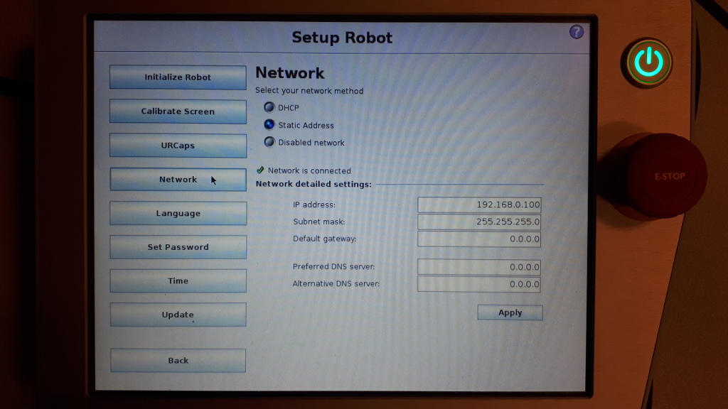
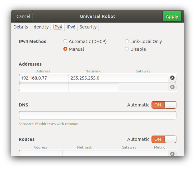
For using ur_rtde you need to prepare the robot.
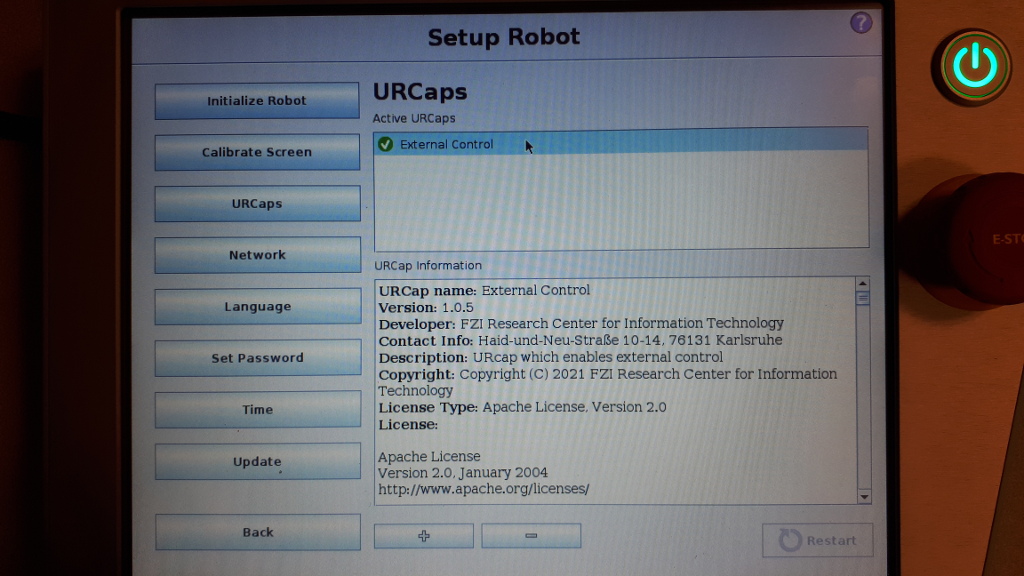
Install the externalcontrol-1.0.5.urcap which can be found here.
For installing the necessary URCap and creating a program, please see the individual tutorials on how to setup a CB3 robot or how to setup an e-Series robot.
On our UR5, using the PolyScope Robot User Interface
To test communication between UR robot and your remote host, you can use testUniversalRobotsGetData.cpp
$ cd $VISP_WS/visp-build/modules/robot
$ ./testUniversalRobotsGetData --ip 192.168.0.100
-- Start test 1/3
Robot connected  : yes
Robot mode       : 3
Robot model      : UR5
PolyScope version: 3.15.7.106331
End test 1/3
-- Start test 2/3
To proceed with this test you need to power on the robot
-- Start test 3/3
...
If you can see a similar output it means that all the prerequisites have been successfully fulfilled.
You can now continue powering the robot on. To this end using PolyScope and entering "Initialize Robot" menu, press "ON" button
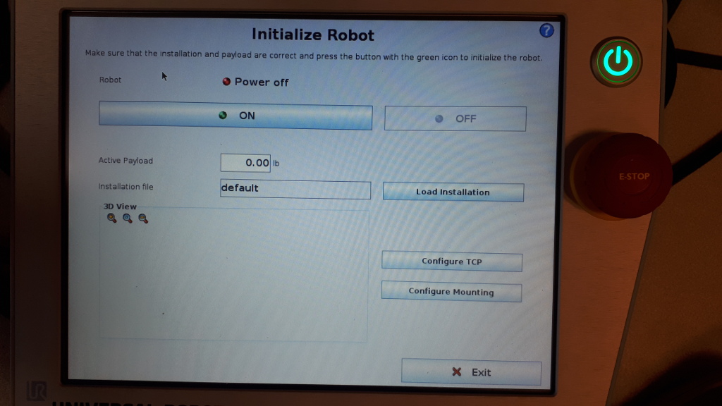
and then run again the test to get robot joint positions:
$ cd $VISP_WS/visp-build/modules/robot
$ ./testUniversalRobotsGetData --ip 192.168.0.100
-- Start test 1/3
Robot connected  : yes
Robot mode       : 5
Robot model      : UR5
PolyScope version: 3.15.7.106331
-- Start test 2/3
Joint position [deg]: -0.05700840128  -89.63515793  91.56270198  -88.23354847  -89.88700067  -0.02810304071
...
Here we consider that you have an UR robot equipped with a Reasense camera. Our model is a Realsense D435 camera, but the tutorial should work with any other Realsense device.
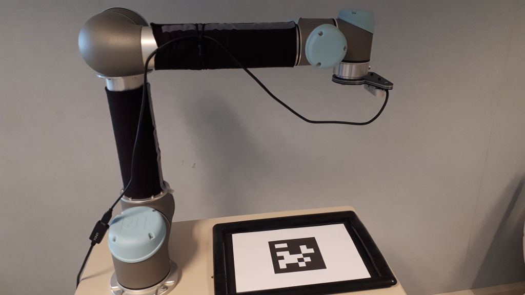
An example of image-based visual servoing using a robot from Universal Robots equipped with a Realsense camera is available in servoUniversalRobotsIBVS.cpp.
 , the homogeneous transformation between robot end-effector and camera frame. We suppose here that the file is located in
 apps/calibration/intrinsic/ur_eMc.yaml.Now enter in example/servo-universal-robots folder and run servoUniversalRobotsIBVS binary using --eMc to locate the file containing the transformation. Other options are available. Using --help show them:
$ cd example/servo-universal-robots
$ ./servoUniversalRobotsIBVS --help
Run the binary activating the plot and using a constant gain:
$ ./servoUniversalRobotsIBVS --eMc ../../apps/calibration/intrinsic/ur_eMc.yaml --plot
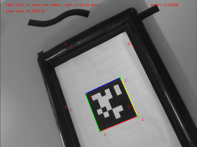
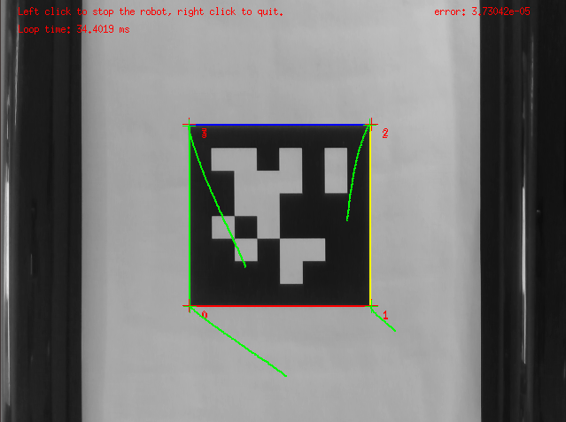
Use the left mouse click to enable the robot controller, and the right click to quit the binary.
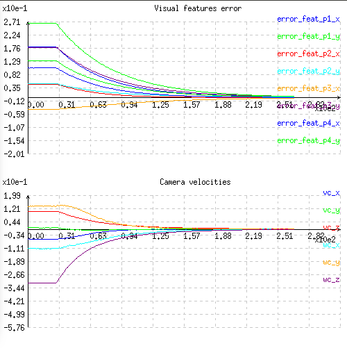
At this point the behaviour that you should observe is the following:
You can also activate an adaptive gain that will make the convergence faster:
$ ./servoUniversalRobotsIBVS --eMc ../../apps/calibration/intrinsic/ur_eMc.yaml --plot --adpative-gain
You can also start the robot with a zero velocity at the beginning introducing task sequencing option:
$ ./servoUniversalRobotsIBVS --eMc ../../apps/calibration/intrinsic/ur_eMc.yaml --plot --task-sequencing
And finally you can activate the adaptive gain and task sequencing:
$ ./servoUniversalRobotsIBVS --eMc ../../apps/calibration/intrinsic/ur_eMc.yaml --plot --adpative-gain --task-sequencing
To learn more about adaptive gain and task sequencing see Tutorial: How to boost your visual servo control law.
To see the differences with a position-based visual-servoing you may also follow Tutorial: PBVS with a robot from Universal Robots.