|
Visual Servoing Platform
version 3.3.0 under development (2020-02-17)
|
|
Visual Servoing Platform
version 3.3.0 under development (2020-02-17)
|
This tutorial explains how to do an image-based servoing with a Parrot Bebop 2 drone on Ubuntu or OSX.
The following material is necessary :
ViSP must be built with OpenCV support if you want to get the video streamed by the drone, which needs to be decoded.
In order to use Parrot Bebop 2 drone with ViSP, you first need to build Parrot's SDK ARDroneSDK3 (as explained here) :
The following steps allow to build ARSDK3 on Ubuntu (tested on 18.04).
1. Get the SDK source code
Create a workspace.
Initialize the repo.
You can then download all the repositories automatically, by executing the following command.
2. Build the SDK
Install required 3rd parties:
Build the SDK:
The output will be located in ${VISP_WS}/ARDroneSDK3/out/arsdk-native/staging/usr
3. Set ARSDK_DIR environment variable
In order for ViSP to find ARDroneSDK3, set ARSDK_DIR environment variable:
4. Modify LD_LIBRARY_PATH environment variable to detect ARDroneSDK3 libraries
In order that ViSP binaries are able to find ARDroneSDK3 libraries, set LD_LIBRARY_PATH with:
The following steps allow to build ARSDK3 on macOS Mojave 10.14.5.
1. Get the SDK source code
Create a workspace.
Initialize the repo.
You can then download all the repositories automatically, by executing the following command.
2. Build the SDK
Install required 3rd parties:
Build the SDK:
The output will be located in ${VISP_WS}/ARDroneSDK3/out/arsdk-native/staging/usr
3. Set ARSDK_DIR environment variable
In order for ViSP to find ARDroneSDK3, set ARSDK_DIR environment variable:
4. Modify DYLD_LIBRARY_PATH environment variable to detect ARDroneSDK3 libraries
In order that ViSP binaries are able to find ARDroneSDK3 libraries, set DYLD_LIBRARY_PATH with:
In order that ViSP takes into account ARSDK3 fresh installation you need to configure and build ViSP again.
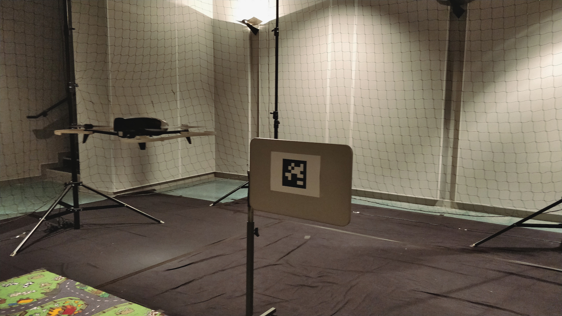
Real robots section that ARSDK and ffmpeg are enabled An example of image-based visual servoing is implemented in servoBebop2.cpp.
The corresponding source code and CMakeLists.txt file can be downloaded using:
First, to get the basics of image-based visual servoing, you can read Tutorial: Image-based visual servo.
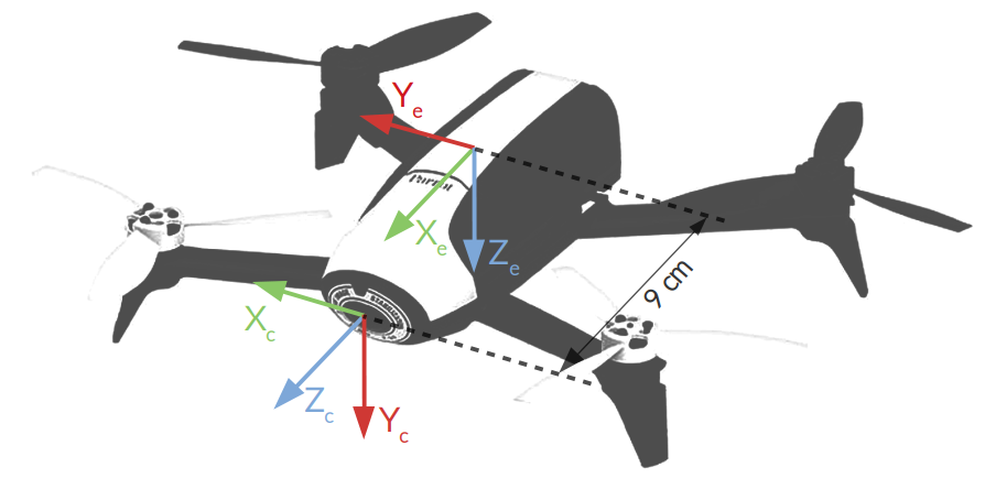
The following image shows the frames attached to the drone:
 corresponding respectively to the 3 translational velocities along
  axis, and the rotational velocity along
  axis. The vpRobotBebop2 class allows to send these velocities. Note that the 6-dim velocity skew vector is named
 axis in which we define the velocities skew vector
  .
. . This transformation is implemented as a vpHomogeneousMatrix.
In servoBebop2.cpp example, we use four visual features  for the servoing in order to control the four drone dof
  . These visual features are:
 of the tag along camera
  and
and  axis. This feature is implemented in vpFeatureMomentGravityCenterNormalized and used to center the tag in the image.
 . This feature implemented in vpFeatureMomentAreaNormalized is used to control the distance between the drone and the tag.
 of this point, we use
  visual feature. This feature implemented in vpFeatureVanishingPoint is used to control the orientation of the drone along its vertical axis based on the tag orientation.
The corresponding controller is given by:
![\[ \dot{\bf q}_e = -\lambda {\left({\bf L_s} {^c}{\bf V}_e {^e}{\bf J}_e\right)}^{+}({\bf s} - {\bf s}^*) \]](form_1371.png)
where:
 is the controller gain implemented in vpAdaptiveGain
 is the interaction matrix corresponding to the visual features
  . This matrix is updated in vpServo
 is the velocity twist matrix build using . Implemented in vpVelocityTwistMatrix it allows to transform a velocity skew from end-effector frame into the camera frame:
 the robot Jacobian that makes the link between the velocity skew and the control dof
  in the end-effector frame:
  and
and  are respectively current and desired visual feature vectors.
To make the relation between this controller description and the code, check the comments in servoBebop2.cpp.
The next step is now to run the image-based visual servoing example implemented in servoBebop2.cpp.
If you built ViSP with ffmpeg and Parrot ARSDK3 support, the corresponding binary is available in ${VISP_WS}/visp-build/example/servo-bebop2 folder.
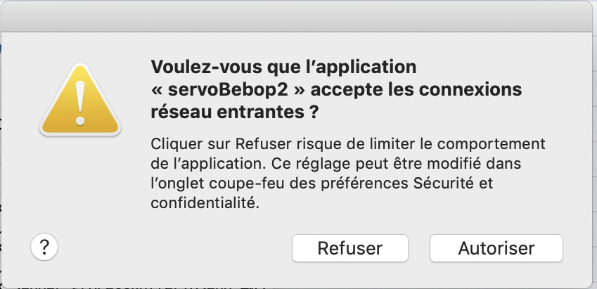
On Mac OSX, you may need to allow servoBebop2 to accept incoming network connections :
Running the previous command should allow to get same results as the one presented in the video:
Run ./servoBebop2 --help to see which are the command line options available.
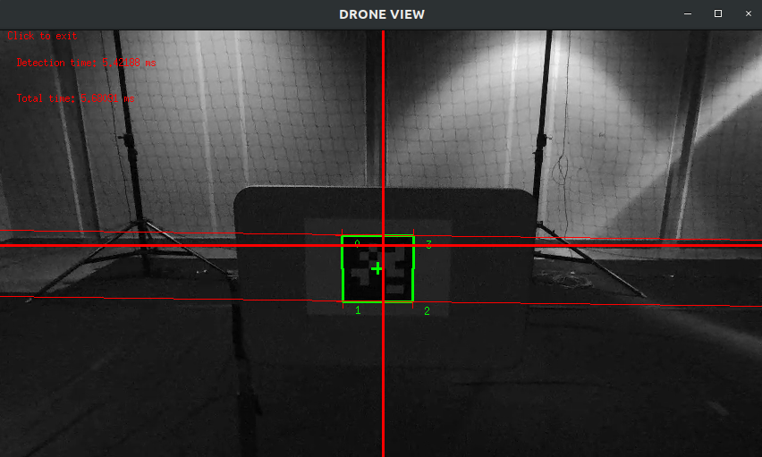
--ip allows you to specify the ip of the drone on the network (default is 192.168.42.1). This is useful if you changed your drone ip (see Changing Bebop 2 IP address), if you want to fly multiple drones at once, for instance.--distance_to_tag 1.5 allows to specify the desired distance (in meters) to the tag for the drone servoing. Values between 0.5 and 2 are recommended (default is 1 meter).--intrinsic ~/path-to-calibration-file/camera.xml allows you to specify the intrinsic camera calibration parameters. This file can be obtained by completing Tutorial: Camera intrinsic calibration. Without this option, default parameters that are enough for a trial will be used..--hd_stream enables HD 720p stream resolution instead of default 480p. Increase range and accuracy of the tag detection, but increases latency and computation time. --verbose or -v enables the display of information messages from the drone, and the velocity commands sent to the drone.The program will first connect to the drone, start the video streaming and decoding, and then the drone will take off and hover until it detects one (and one only) 36h11 AprilTag in the image.
We then display the drone video stream with the visible features, as well as the error for each feature :
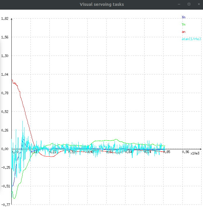
In this graph :
 that allows to control the tag center of gravity along axis,
 that allows to control the tag center of gravity along axis,
 , used to regulate the distance between the drone and the tag along
  axis,
axis, related to vanishing point. This feature will make the drone move its orientation along axis to ensure that the two horizontal lines remain parallel.
Clicking on the drone view display will make the drone land, safely disconnect everything and quit the program.
If you need to change the drone IP address, for flying multiple drones for instance, you can follow these steps :
/sbin/broadcom_setup.sh : VI text editor :i and escape to cancel,: and enter wq to save and quit, or q! to quit without saving.IFACE IP AP=”192.168.42.1” to IFACE IP AP=”192.168.x.1”, where x represents any number that you have not assigned to any other drone yet.exit.If you want to control multiple drones using one single computer, you're going to need to change the drones ip, by following Changing Bebop 2 IP address.
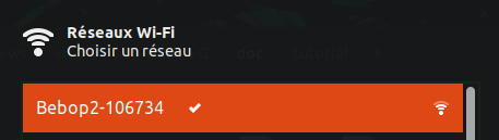
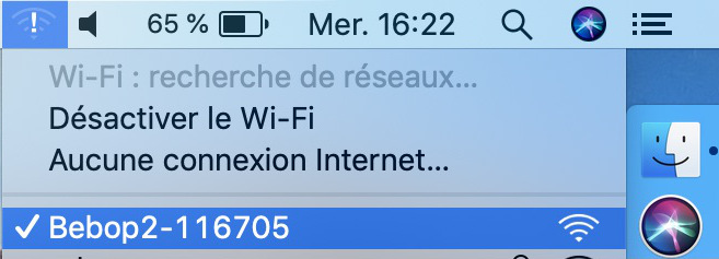
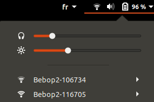
Once every drone you want to use has a unique IP address, you need to connect your PC to each drone WiFi network. You can use multiple WiFi dongles and you PC WiFi card, if it has one.
For two drones, it should look like this (on Ubuntu) :
In ViSP programs that use the drone, you can then use option --ip to specify the IP of the drone to which you want to connect :
and in another terminal :
In your own programs, you can specify the IP in the constructor of vpRobotBebop2 class :
If needed, you can see Tutorial: Image frame grabbing corresponding section dedicated to Parrot Bebop 2 to get images of the calibration grid.
You can also calibrate your drone camera and generate an XML file usable in the servoing program (see Tutorial: Camera intrinsic calibration).
If you need more details about this program, check the comments in servoBebop2.cpp.
You can check example program keyboardControlBebop2.cpp if you want to see how to control a Bebop 2 drone with the keyboard.
You can also check vpRobotBebop2 to see the full documentation of the Bebop 2 ViSP class.
Finally, if you are more interested to do the same experiment with ROS framework, you can follow How to do visual servoing with Parrot Bebop 2 drone using visp_ros tutorial.
 1.8.13