|
Visual Servoing Platform
version 3.5.0 under development (2022-02-15)
|
|
Visual Servoing Platform
version 3.5.0 under development (2022-02-15)
|
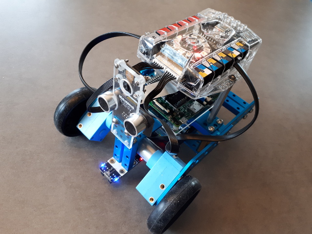
This tutorial explains how to do a position-based visual-servoing with the mBot Ranger educational robot kit equipped with a Raspberry Pi 3 board connected to a camera.
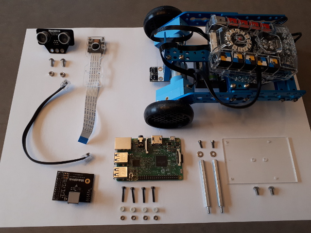
The following material is requested:
The communication between Raspberry Pi and mBot Auriga board is achieved via a serial link. Images acquired on the Raspberry Pi are processed in order to detect the AprilTag pose. From this pose a visual-servoing computes the velocities that have to be send to the Me Auriga. On the Me Auriga there is an infinite loop that is waiting for velocities that have to be applied to the Dashing Raptor wheels. A watch dog ensure the mobile robot stops when nothing is sent throw the serial link after 1 second.
The following video shows the result of this tutorial; the mBot Ranger follows the AprilTag target in order to maintain a given distance between the tag and the camera.
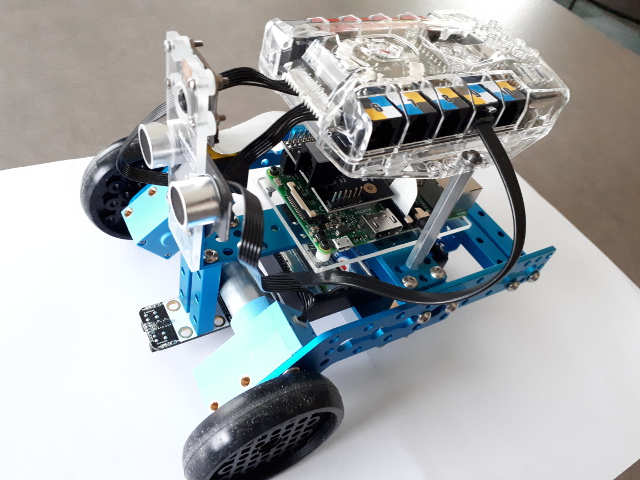
The following image shows the material that we use to build the robot:
First you need to follow these instructions to mount the Dashing Raptor.
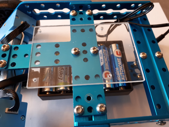
Mount the camera on the plexiglass support
As shown in the next image, we build a plexiglass support with external dimensions 26 mm by 85 mm
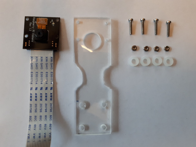
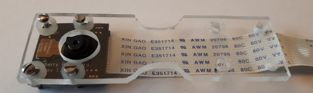
Fix the camera on its support
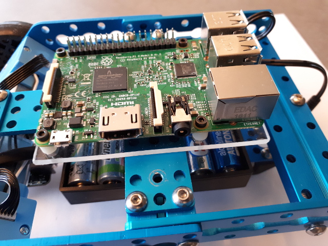
Mount the Raspberry Pi We use a plexiglass support with dimensions 60 mm by 90 mm to fix the Raspberry Pi on the Dashing Raptor.
Mount the plexiglass support
Mount the Raspberry Pi
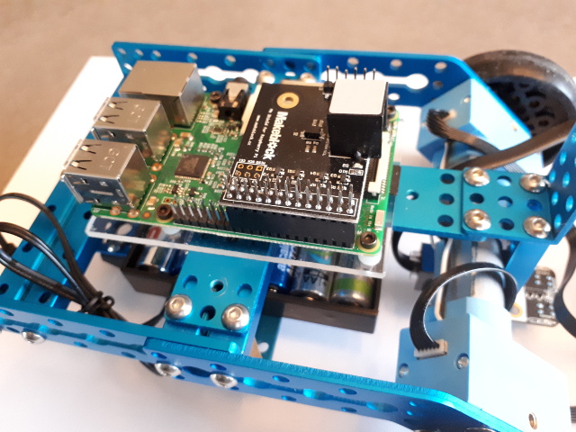
Plug the Me Shield
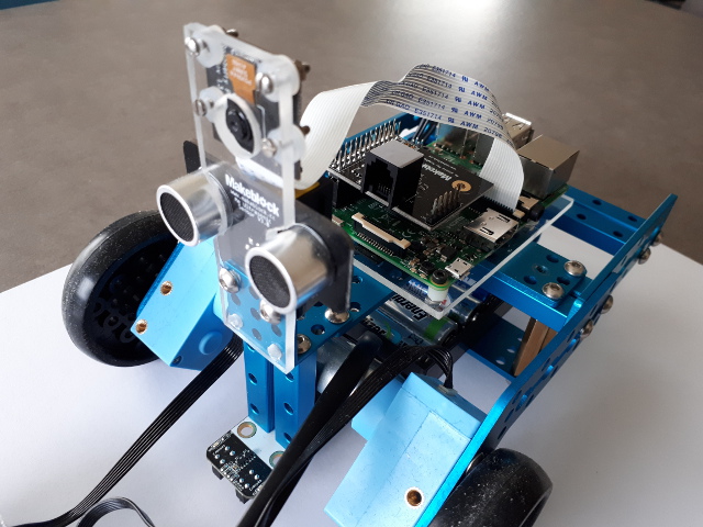
Plug the camera on the Raspberry Pi and screw the camera support on the robot
Mount the Me Auriga over the Raspberry Pi
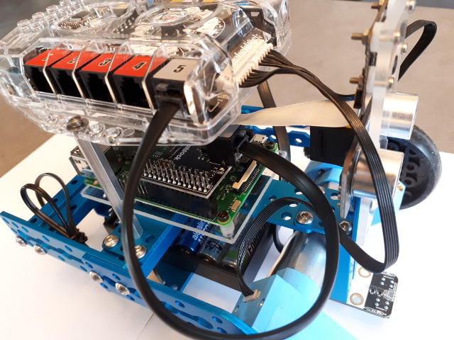
Plug the cable between Me Shield and Me Auriga port 5
mBlock is a graphical programming software which is designed based on Scratch and compatible with Arduino boards such as Makeblock board like the Me Auriga. Visit the following URL for more details: http://learn.makeblock.com/getting-started-programming-with-mblock-2/. We suggest also to follow the getting started courses http://learn.makeblock.com/ranger-online-course/ if you are not familiar with mBot and mBlock.
These are the steps to work on Windows, with mBlock:
Start menu > mBlock > mBlockConnect > Serial Port shows COM3)Connect > Serial Port menu (in our case COM4)Connect > Serial Port > COM4. You should hear a new beepInstall Arduino Library for Makeblock Electronic Modules as described in https://github.com/Makeblock-official/Makeblock-Libraries.
To resume:
C:> cd C:\temp
C:> git clone https://github.com/Makeblock-official/Makeblock-Libraries
Then copy C:\temp\Makeblock-Libraries\makeblock into C:\Program Files (x86)\mBlock\Arduino\libraries. This copy requires administration rights.
In ViSP we provide in tutorial/robot/mbot/mblock/test-ring-led.sb2 an mBlock test that is be useful to check if the ME Auriga board is working as expected. To get this file, use Subversion (even if code is handled with git):
$ svn export https://github.com/lagadic/visp.git/trunk/tutorial/robot/mbot/mblock
To achieve the test:
File > Load Project to load test-ring-led.sb2. 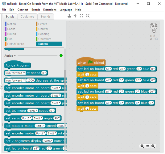
Connect > Upgrade Firmware. When the upload is finished you should hear a beepWe provide mbot-serial-controller.ino file that contains our controller written in Arduino. It has to be compiled and uploaded on Me Auriga board. This file is part of ViSP and located in tutorial/robot/mbot/arduino/mbot-serial-controller.
Get the source code using:
C:/> mkdir C:\visp-mblock
C:/> cd C:\visp-mblock
C:/> svn export https://github.com/lagadic/visp.git/trunk/tutorial/robot/mbot/arduino
The controller implemented in mbot-serial-controller.ino enables the serial link at 115200 baud and also the motors. In the loop() when a serial data is available with the MOTOR_RPM keyword it applies the corresponding motor velocity to the left and right wheels, and with the LED_RING keyword it turn the ring led on with the corresponding color or off.
To compile and upload this controller to the Me Auriga board:
Edit > Arduino mode to open the Arduino panel 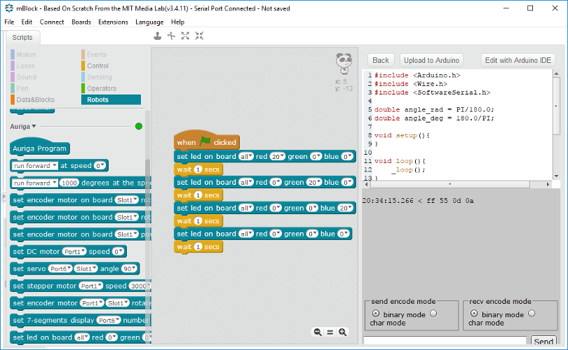
Edit with Arduino IDE. It will open the Arduino IDE.File > Open to open mbot-serial-controller.ino 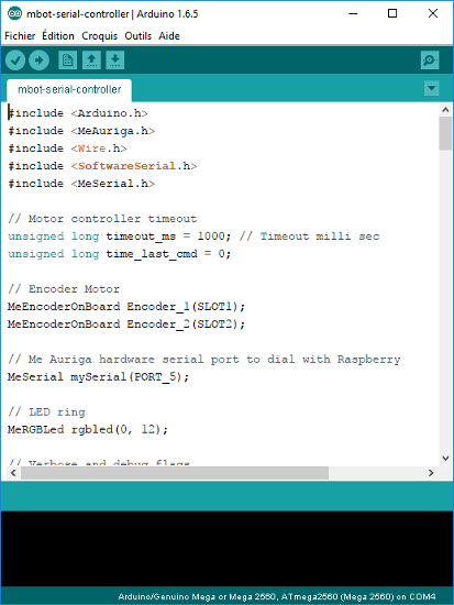
Tool > Board menu that should be set to Arduino/Genuino Mega or Mega 2560, and also the correct port from the Tool > Port menu; in our case COM4.Sketch > Upload.Since in this tutorial we want to control the motors, you need to connect an external power supply using for example six 1.5 Volt batteries.
In this section we will see how to configure the serial port on Raspberry Pi in order to use the serial port /dev/ttyAMA0 to communicate. Depending on your Raspebrry Pi version this is slightly different.
This section is inspired from this tutorial. The following instructions resume what has to be done.
The GPIO serial port is disabled by default. In order to enable it, edit /boot/config.txt and add the line enable_uart=1 at the bottom:
$ sudo nano /boot/config.txt
enable_uart=1
Disabling the Console:
$ sudo systemctl stop serial-getty@ttyS0.service
$ sudo systemctl disable serial-getty@ttyS0.service
You also need to remove the console from the /boot/cmdline.txt. If you edit this with:
$ sudo nano /boot/cmdline.txt
You will see something like:
dwc_otg.lpm_enable=0 console=serial0,115200 console=tty1 root=/dev/mmcblk0p7 rootfstype=ext4 elevator=deadline fsck.repair=yes rootwait
Remove console=serial0,115200, save and reboot for changes to take effect.
Swapping the serial ports on Raspberry Pi 3
$ ll /dev/serial*
lrwxrwxrwx 1 root root 5 Mar 10 13:30 /dev/serial0 -> ttyS0
lrwxrwxrwx 1 root root 7 Mar 10 13:30 /dev/serial1 -> ttyAMA0
To swap the serial ports ttyS0 and ttyAMA0 add the following line to the /boot/config.txt
$ sudo nano /boot/config.txt
and add:
dtoverlay=pi3-miniuart-bt
Save and reboot for changes to take effect.
You can check that it has worked by:
$ ls -l /dev/serial*
and you’ll see something like this:
lrwxrwxrwx 1 root root 7 Mar 10 22:00 /dev/serial0 -> ttyAMA0
lrwxrwxrwx 1 root root 5 Mar 10 22:00 /dev/serial1 -> ttyS0
We provide hereafter the instructions to configure the serial port on Raspberry Pi 1 or 2 if you don't have a Pi 3 under the hand.
To be able to use the serial port to connect and talk to other devices (e.g. in our case the Me Auriga), the serial port console login needs to be disabled.
If this is the case, you should see something similar to:
$ ssh -Y pi@raspberry
$ dmesg | grep ttyAMA0
[    0.509769] console [ttyAMA0] enabled
As described in this tutorial to disable the console on ttyAMA0 do the following:
$ sudo raspi-config
7 Advanced Options > A8 Serial > Would you like a login shell to be accessible over serial > No
Serial is now disable > Ok
Output is now as expected:
$ dmesg | grep ttyAMA0
[    0.135617] 20201000.uart: ttyAMA0 at MMIO 0x20201000 (irq = 83, base_baud = 0) is a PL011 rev2
First of all, with the Pi switched off, you’ll need to connect the Camera Module to the Raspberry Pi’s camera port, then start up the Pi and ensure the software is enabled.
This could be achieved following this tutorial or this tutorial.
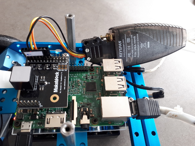
Here we use our Raspberry Pi 3 connected to an external power supply, a RS232/TTL 3-5,5V adapter and a home made adapter that is used to connect the RS232/TTL 3-5,5V adapter to the Raspberry Pi GPIO connector. The home made adapter connects Raspberry PI GPIO pins 6 (GND), 8 (TxD UART), 10 (RxD UART) to a RS232 DB9 female connector.
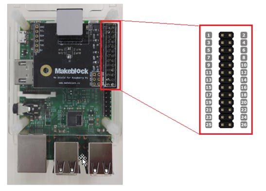
The following image shows the Me Shield pinout
while the next image shows the usage:
The following table shows the wiring pinout:
Now we can use two python files, test-serial-write.py who writes something on the /dev/ttyAMA0 port and the test-serial-read.py that reads on a laptop running Ubuntu 16.04 on /dev/ttyUSB0 port.
To get these files use Subversion (even if code is handled with git):
$ sudo apt-get install subversion
$ svn export https://github.com/lagadic/visp.git/trunk/tutorial/robot/mbot/raspberry/python
/home/pi/visp-ws/visp/robot/mbot/raspberry/python.After plugging the ME Shield to the Raspberry Pi and connecting the home made adapter to yo your laptop, you can test if you succeed to configure Raspberry Pi serial port, running on your laptop:
$ sudo chmod a+rw /dev/ttyUSB0
$ python test-serial-read.py
not blocked
not blocked
not blocked
Got 5: data: <non alpha characters>
not blocked
and on the Raspberry Pi
$ python test-serial-write.py
After running test-serial-write.py you should see lines like Got 5: data: <non alpha characters> on the laptop side.
To test if you are able to acquire images from your RPi camera and detect your Apriltag, you may run tutorial-apriltag-detector-live.cpp. If you build ViSP from source as explained in Tutorial: Installation from source for Raspberry Pi the corresponding binary is available in /home/pi/visp-ws/visp-build/tutorial/detection/tag.
To run this test on the Raspberry Pi:
$ cd /home/pi/visp-ws/visp-build/tutorial/detection/tag
$ ./tutorial-apriltag-detector-live
We suppose here that you have Upload the controller. The communication between the uploaded mBot controller and Raspberry Pi is achieved by a serial link using RPi /dev/ttyAMA0 port configured with the following parameters: 115200 baud, 8 bits, parity none, 1 stop bit and no control flow.
We implement a basic communication protocol with the following keywords MOTOR_RPM and LED_RING. Each keyword has a set of parameters with comma as separator. The R,G,B color level is in range 0-255.
The following sample code shows how to send instructions from Raspberry Pi to mBot controller to turn left wheel at -100 round per minute (RPM), right wheel at 100 RPM, and turn all the ring led on with green intensity set to 10. After 5 seconds, the ring led is turned off. Since in the mBot controller we implement a watch dog, the motors will be stop automatically by the watchdog.
We provide a test in test-serial-mbot.cpp that allows to check if instructions send from the Raspberry Pi to the mBot Ranger by serial link is working. If you build ViSP from source as explained in Tutorial: Installation from source for Raspberry Pi the corresponding binary is available in /home/pi/visp-ws/visp/robot/mbot/raspberry/visp.
Run first this test on the Raspberry Pi with --help option:
$ cd /home/pi/visp-ws/visp/robot/mbot/raspberry/visp
$ ./test-serial-mbot --help
Usage:
./test-serial-mbot --vx <linear velocity in m/s> --wz <rotational velocity in deg/s> --rpm_l <motor left RPM> --rpm_r <motor right RPM> --t <duration of the command in second> --help

Example:
./test-serial-mbot --vx 0.05 --wz 0 --t 4
You can now try to send a linear velocity of 5 cm/s during 4 sec to the robot using:
$ ./test-serial-mbot --vx 0.05 --wz 0 --t 4
Apply v_x=0.05 m/s  w_z=0 deg/s during 4 seconds
Motor left vel: -1.53846 motor right vel: 1.53846 (rad/s)
Send: MOTOR_RPM=-14,14
The next step is now to run the image-based visual servoing example implemented in mbot-apriltag-ibvs.cpp. In this example we use two image moments as visual features and especially the normalized gravity center along  axis implemented in vpFeatureMomentGravityCenterNormalized and the normalized area implemented in vpFeatureMomentAreaNormalized. The first one allows to control the orientation of the robot to maintain the target on a vertical line in the middle of the image, while the second feature allows to regulate the distance wrt the target. These features are interesting here since they don't require any 3D information to compute the error vector or the interaction matrix.
If you build ViSP from source as explained in Tutorial: Installation from source for Raspberry Pi the corresponding binary is available in /home/pi/visp-ws/visp-build/tutorial/robot/mbot/raspberry/visp/.
$ cd /home/pi/visp-ws/visp-build/tutorial/robot/mbot/raspberry/visp
$ ./mbot-apriltag-ibvs
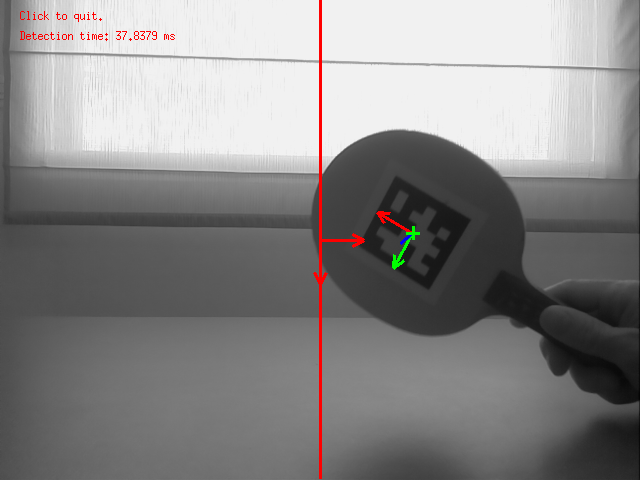
Run ./mbot-apriltag-ibvs --help to see which are the command line options available. Adding option --display_on allows to display images like the following that shows the result of the image processing and features that are used:
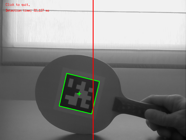
Since using this option could introduce a lag due to the network connection, we recommend to use it only for curiosity.
We provide also a 2D half visual servoing example implemented in mbot-apriltag-2D-half-vs.cpp. This example uses a mix between 2D and 3D visual features and especially the 2D coordinate of the target cog implemented in vpFeaturePoint and the depth feature implemented in vpFeatureDepth. The first one allows to control the orientation of the robot to maintain the target on a vertical line in the middle of the image, while the second feature allows to regulate the distance Z wrt the target.
The corresponding binary is available in /home/pi/visp-ws/visp-build/tutorial/robot/mbot/raspberry/visp/.
$ cd /home/pi/visp-ws/visp-build/tutorial/robot/mbot/raspberry/visp
$ ./mbot-apriltag-2D-half-vs
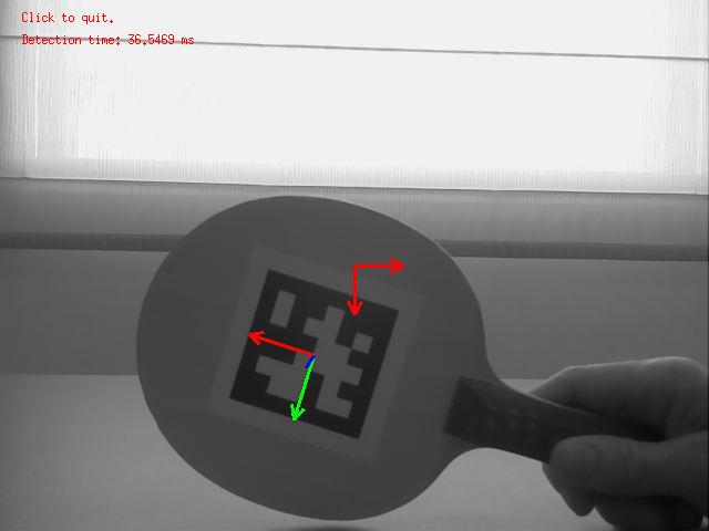
Run ./mbot-apriltag-2D-half-vs --help to see which are the command line options available. Adding option --display_on allows to display images like the following that shows the result of the image processing and features that are used:
Since using this option could introduce a lag due to the network connection, we recommend to use it only for curiosity.
We provide also a position-based visual servoing example implemented in mbot-apriltag-pbvs.cpp. Here we use pure 3D visual features implemented in vpFeaturePoint3D and especially X and Z values obtained from the pose of the tag.
The corresponding binary is available in /home/pi/visp-ws/visp-build/tutorial/robot/mbot/raspberry/visp/.
$ cd /home/pi/visp-ws/visp-build/tutorial/robot/mbot/raspberry/visp
$ ./mbot-apriltag-pbvs
Run ./mbot-apriltag-pbvs --help to see which are the command line options available. Adding option --display_on allows to display images like the following that shows the result of the image processing and features that are used:
Since using this option could introduce a lag due to the network connection, we recommend to use it only for curiosity.
It is possible to transform the mbot-apriltag-2D-half-vs demo into a service on the Raspberry Pi in order to start the binary when raspberry has booted. To this end, we need to install a daemon. This example uses a 3D visual features and especially the  3D coordinate of the target 3D frame implemented in vpFeaturePoint3D and the depth feature implemented in vpFeatureDepth. The first one allows to control the orientation of the robot to maintain the target origin frame on a vertical line in the middle of the image, while the second feature allows to regulate the distance Z wrt the target.
If you follow Tutorial: Installation from source for Raspberry Pi, there is already a daemon in /home/pi/visp-ws/visp/tutorial/robot/mbot/raspberry/daemon. You need to edit visual-servo file and adapt the location of the visual-servo binary location.
DAEMON="/home/pi/visp-ws/visp-build/tutorial/robot/mbot/raspberry/visp/mbot-apriltag-ibvs"
Install the daemon
$ sudo cp /home/pi/visp-ws/visp/tutorial/robot/mbot/raspberry/daemon/visual-servo /etc/init.d
$ sudo chmod 0755 /etc/init.d/visual-servo
Reboot or reload the daemon
$ sudo systemctl daemon-reload
Testing the daemon
$ sudo /etc/init.d/visual-servo start
$ sudo /etc/init.d/visual-servo stop
Now we can add the service at startup
$ sudo update-rc.d visual-servo defaults
To remove the service
$ sudo update-rc.d visual-servo remove
 1.8.13