Visual Servoing Platform  version 3.3.0 under development (2020-02-17)
Tutorial: Markerless generic model-based tracking using a RGB-D camera

Introduction

This tutorial describes how to use the generic markerless model-based tracker [7], [40] implemented in vpMbGenericTracker with data acquired by a RGB-D camera like the Intel RealSense devices (SR300 or D400 series). You are advised to have read the Tutorial: Markerless generic model-based tracking using a color camera to have an overview of the generic model-based tracker working on images acquired by a color camera that uses moving-edges and keypoints as visual features. We suggest also to follow Tutorial: Markerless generic model-based tracking using a stereo camera to learn how to consider stereo cameras, since a RGB-D camera is in a sense a stereo camera, with the left camera providing the color image and the right the depth image.

Note that all the material (source code, input video, CAD model or XML settings files) described in this tutorial is part of ViSP source code and could be downloaded using the following command:

$ svn export https://github.com/lagadic/visp.git/trunk/tutorial/tracking/model-based/generic-rgbd

Features overview

Considering the use case of a RGB-D camera, the tracker implemented in vpMbGenericTracker class allows to consider a combination of the following visual features:

  • moving edges: contour points tracked along the normals of the visible edges defined in the CAD model (line, face, cylinder and circle primitives) [7]
  • keypoints: they are tracked on the visible object faces using the KLT tracker (face and cylinder primitives) [35]
  • depth normal: the normal of a face computed from the depth map (face primitives) (since ViSP 3.1.0)
  • depth dense: the dense pointcloud obtained from the depth map (face primitives) (since ViSP 3.1.0) [40].

The moving-edges and KLT features require a RGB camera, more precisely these features operate on grayscale image. The depth normal and dense depth features require a depth map that can be obtained from a RGB-D camera for example.

If you want to use a depth feature, we advise you to choose the dense depth features that is a much more robust method compared to the depth normal feature. Keep also in mind that Kinect-like sensors have a limited depth range (from ~0.8m to ~3.5m).

Note also that combining the visual features can be a good way to improve the tracking robustness (e.g. a stereo tracker with moving edges + keypoints for the left camera and dense depth visual features for the right camera).

The following video demonstrates the use of the generic tracker with a RGB-D sensor using the following features:

  • moving-edges + keypoints features for the color camera
  • depth normal features for the depth sensor

In this video, the same setup is used but with:

  • moving-edges features for the color camera
  • dense depth features for the depth sensor

Considered third-parties

Depending on your use case the following optional third-parties may be used by the tracker. Make sure ViSP was build with the appropriate 3rd parties:

  • OpenCV: Essential if you want to use the keypoints as visual features that are detected and tracked thanks to the KLT tracker. This 3rd party may be also useful to consider input videos (mpeg, png, jpeg...).
  • Point Cloud Library: This 3rd party is optional but could be used if your RGB-D sensor provides the depth data as a point cloud. Notice that the source code explained in this tutorial doesn't run if you don't have a version of ViSP build with PCL as 3rd party. Note also that you don't need to install PCL if you don't want to consider depth as visual feature.
  • Ogre 3D: This 3rd party is optional and could be difficult to install on OSX and Windows. To begin with the tracker we don't recommend to install it. Ogre 3D allows to enable Advanced visibility via Ogre3D.
  • Coin 3D: This 3rd party is also optional and difficult to install. That's why we don't recommend to install Coin 3D to begin with the tracker. Coin 3D allows only to consider CAD model in wrml format instead of the home-made CAD model in cao format.

It is recommended to install an optimized BLAS library (for instance OpenBLAS) to get better performance with the dense depth feature approach which requires large matrix operations. On Ubuntu Xenial, it is the libopenblas-dev package that should be installed. To select or switch the BLAS library to use, see Handle different versions of BLAS and LAPACK:

$ update-alternatives --config libblas.so.3

You should have something similar to this:

There are 3 choices for the alternative libblas.so.3 (providing /usr/lib/libblas.so.3).

Selection Path Priority Status
0 /usr/lib/openblas-base/libblas.so.3 40 auto mode
1 /usr/lib/atlas-base/atlas/libblas.so.3 35 manual mode
2 /usr/lib/libblas/libblas.so.3 10 manual mode
3 /usr/lib/openblas-base/libblas.so.3 40 manual mode

Input data

For classical features working on grayscale image, you have to use the following data type:

You can convert to a grayscale image if the image acquired is in RGBa data type:

// Color image acquisition

For depth features, you need to supply a pointcloud, that means a 2D array where each element contains the X, Y and Z coordinate in the depth sensor frame. The following data type are accepted:

  • a vector of vpColVector: the column vector being a 3x1 (X, Y, Z) vector
    std::vector<vpColVector> pointcloud(640*480);
    // Fill the pointcloud
    vpColVector coordinate(3);
    coordinate[0] = X;
    coordinate[1] = Y;
    coordinate[2] = Z;
    pointcloud[0] = coordinate;
  • a PCL pointcloud smart pointer of pcl::PointXYZ data type:
    pcl::PointCloud<pcl::PointXYZ>::Ptr pointcloud;

If you have only a depth map, a 2D array where each element (u, v) is the distance Z in meter between the depth sensor frame to the object, you will need to compute the 3D coordinates using the depth sensor intrinsic parameters. We recall that u relates to the array columns, while v relates to the array rows. For instance, without taking into account the distortion (see also vpPixelMeterConversion::convertPoint), the conversion is (u and v are the pixel coordinates, u0, v0, px, py are the intrinsic parameters):

\[ \left\{\begin{matrix} X = \frac{u - u_0}{px} \times Z \\ Y = \frac{v - v_0}{px} \times Z \end{matrix}\right. \]

Here an example of a depth map:

tutorial-tracking-mb-generic-depth-map.png

Getting started

Implementation detail

Note
This section is similar to the Implementation detail section in Tutorial: Markerless generic model-based tracking using a stereo camera.

Each tracker is stored in a map, the key corresponding to the name of the camera on which the tracker will process. By default, the camera names are set to:

  • "Camera" when the tracker is constructed with one camera.
  • "Camera1" to "CameraN" when the tracker is constructed with N cameras.
  • The default reference camera will be "Camera1" in the multiple cameras case.
img-multi-cameras-config.png
Default name convention and reference camera ("Camera1").

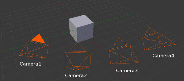
To deal with multiple cameras, in the virtual visual servoing control law we concatenate all the interaction matrices and residual vectors and transform them in a single reference camera frame to compute the reference camera velocity. Thus, we have to know the transformation matrix between each camera and the reference camera.

For example, if the reference camera is "Camera1" ( $ c_1 $), we need the following information: $ _{}^{c_2}\textrm{M}_{c_1}, _{}^{c_3}\textrm{M}_{c_1}, \cdots, _{}^{c_n}\textrm{M}_{c_1} $.

Declare a model-based tracker of the desired feature type

The following enumeration (vpMbGenericTracker::vpTrackerType) values are available to get the desired model-based tracker:

The tracker declaration is then:

To combine the features:

To "fully exploit" the capabilities of a RGB-D sensor, you can use for instance:

std::vector<int> trackerTypes(2);
vpMbGenericTracker tracker(trackerTypes);

This will declare a tracker with edge + KLT features for the color camera and dense depth feature for the depth sensor.

Interfacing with the code

Note
This section is more or less similar to the Interfacing with the code section in Tutorial: Markerless model-based tracking with stereo cameras (deprecated)

Each essential method used to initialize the tracker and process the tracking have three signatures in order to ease the call to the method and according to three working modes:

  • tracking using one camera, the signature remains the same.
  • tracking using two cameras, all the necessary methods accept directly the corresponding parameters for each camera.
  • tracking using multiple cameras, you have to supply the different parameters within a map. The key corresponds to the name of the camera and the value is the parameter.

The following table sums up how to call the different methods based on the camera configuration for the main functions.

Example of the different method signatures.
Method calling example: Monocular case Stereo case Multiple cameras case Remarks
Construct a model-based edge tracker: vpMbGenericTracker tracker vpMbGenericTracker tracker(2, vpMbGenericTracker::EDGE_TRACKER) vpMbGenericTracker tracker(5, vpMbGenericTracker::EDGE_TRACKER) The default constructor corresponds to a monocular edge tracker.
Load a configuration file: tracker.loadConfigFile("config.xml") tracker.loadConfigFile("config1.xml", "config2.xml") tracker.loadConfigFile(mapOfConfigFiles) Each tracker can have different parameters (intrinsic parameters, visibility angles, etc.).
Load a model file: tracker.loadModel("model.cao") tracker.loadModel("model1.cao", "model2.cao") tracker.loadModel(mapOfModelFiles) Different models can be used.
Get the intrinsic camera parameters: tracker.getCameraParameters(cam) tracker.getCameraParameters(cam1, cam2) tracker.getCameraParameters(mapOfCam)
Set the transformation matrix between each camera and the reference one: tracker.setCameraTransformationMatrix(mapOfCamTrans) tracker.setCameraTransformationMatrix(mapOfCamTrans) For the reference camera, the identity homogeneous matrix must be used.
Setting to display the features: tracker.setDisplayFeatures(true) tracker.setDisplayFeatures(true) tracker.setDisplayFeatures(true) This is a general parameter.
Initialize the pose by click: tracker.initClick(I, "f_init.init") tracker.initClick(I1, I2, "f_init1.init", "f_init2.init") tracker.initClick(mapOfImg, mapOfInitFiles) Assuming the transformation matrices between the cameras have been set, some init files can be omitted as long as the reference camera has an init file. The corresponding images must be supplied.
Track the object: tracker.track(I) tracker.track(I1, I2) tracker.track(mapOfImg) See the documentation to track with pointcloud.
Get the pose: tracker.getPose(cMo) tracker.getPose(c1Mo, c2Mo) tracker.getPose(mapOfPoses) tracker.getPose(cMo) will return the pose for the reference camera in the stereo/multiple cameras configurations.
Display the model: tracker.display(I, cMo, cam, ...) tracker.display(I1, I2, c1Mo, c2Mo, cam1, cam2, ...) tracker.display(mapOfImg, mapOfPoses, mapOfCam, ...)
Note
As the trackers are stored in an alphabetic order internally, you have to match the method parameters with the correct tracker position in the map in the stereo cameras case.

Example code

Tracking a cube with RGB-D data

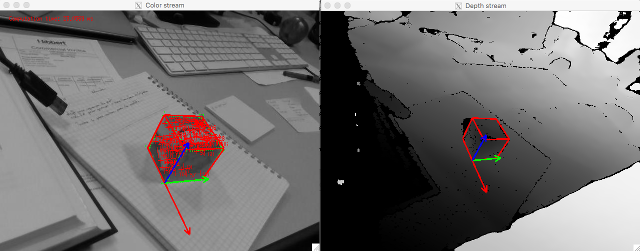
We provide hereafter an example implemented in tutorial-mb-generic-tracker-rgbd.cpp that shows how to track a cube modeled in cao format using moving-eges, keypoints and dense depth as visual features. The input data (color image, depth map and point clould) were acquired by a RealSense RGB-D camera.

Warning
ViSP must have been built with OpenCV and the KLT module must be enabled to run this tutorial. You need also the Point Cloud Library enabled.

Once built, run the binary:

$ ./tutorial-mb-generic-tracker-rgbd

After initialization by 4 user clicks, the tracker is running and produces the following output:

img-mbt-rgbd-cube.png

The source code that is very similar to the one provided in Tutorial: Markerless generic model-based tracking using a stereo camera is the following:

#include <iostream>
#include <visp3/core/vpDisplay.h>
#include <visp3/core/vpIoTools.h>
#include <visp3/io/vpImageIo.h>
#include <visp3/core/vpXmlParserCamera.h>
#include <visp3/gui/vpDisplayGDI.h>
#include <visp3/gui/vpDisplayX.h>
#include <visp3/mbt/vpMbGenericTracker.h>
#if defined (VISP_HAVE_PCL)
#include <pcl/common/common.h>
#include <pcl/io/pcd_io.h>
namespace {
struct rs_intrinsics {
float ppx;
float ppy;
float fx;
float fy;
float coeffs[5];
};
void rs_deproject_pixel_to_point(float point[3], const rs_intrinsics &intrin, const float pixel[2], float depth) {
float x = (pixel[0] - intrin.ppx) / intrin.fx;
float y = (pixel[1] - intrin.ppy) / intrin.fy;
float r2 = x * x + y * y;
float f = 1 + intrin.coeffs[0] * r2 + intrin.coeffs[1] * r2 * r2 + intrin.coeffs[4] * r2 * r2 * r2;
float ux = x * f + 2 * intrin.coeffs[2] * x * y + intrin.coeffs[3] * (r2 + 2 * x * x);
float uy = y * f + 2 * intrin.coeffs[3] * x * y + intrin.coeffs[2] * (r2 + 2 * y * y);
x = ux;
y = uy;
point[0] = depth * x;
point[1] = depth * y;
point[2] = depth;
}
bool read_data(unsigned int cpt, const std::string &input_directory, vpImage<vpRGBa> &I_color,
vpImage<uint16_t> &I_depth_raw, pcl::PointCloud<pcl::PointXYZ>::Ptr &pointcloud)
{
char buffer[FILENAME_MAX];
// Read color
std::stringstream ss;
ss << input_directory << "/color_image_%04d.jpg";
sprintf(buffer, ss.str().c_str(), cpt);
std::string filename_color = buffer;
if (!vpIoTools::checkFilename(filename_color)) {
std::cerr << "Cannot read: " << filename_color << std::endl;
return false;
}
vpImageIo::read(I_color, filename_color);
// Read raw depth
ss.str("");
ss << input_directory << "/depth_image_%04d.bin";
sprintf(buffer, ss.str().c_str(), cpt);
std::string filename_depth = buffer;
std::ifstream file_depth(filename_depth.c_str(), std::ios::in | std::ios::binary);
if (!file_depth.is_open()) {
return false;
}
unsigned int height = 0, width = 0;
vpIoTools::readBinaryValueLE(file_depth, height);
vpIoTools::readBinaryValueLE(file_depth, width);
I_depth_raw.resize(height, width);
uint16_t depth_value = 0;
for (unsigned int i = 0; i < height; i++) {
for (unsigned int j = 0; j < width; j++) {
vpIoTools::readBinaryValueLE(file_depth, depth_value);
I_depth_raw[i][j] = depth_value;
}
}
// Transform pointcloud
pointcloud->width = width;
pointcloud->height = height;
pointcloud->reserve((size_t)width * height);
// Only for Creative SR300
const float depth_scale = 0.00100000005f;
rs_intrinsics depth_intrinsic;
depth_intrinsic.ppx = 320.503509521484f;
depth_intrinsic.ppy = 235.602951049805f;
depth_intrinsic.fx = 383.970001220703f;
depth_intrinsic.fy = 383.970001220703f;
depth_intrinsic.coeffs[0] = 0.0f;
depth_intrinsic.coeffs[1] = 0.0f;
depth_intrinsic.coeffs[2] = 0.0f;
depth_intrinsic.coeffs[3] = 0.0f;
depth_intrinsic.coeffs[4] = 0.0f;
for (unsigned int i = 0; i < height; i++) {
for (unsigned int j = 0; j < width; j++) {
float scaled_depth = I_depth_raw[i][j] * depth_scale;
float point[3];
float pixel[2] = {(float)j, (float)i};
rs_deproject_pixel_to_point(point, depth_intrinsic, pixel, scaled_depth);
pointcloud->push_back(pcl::PointXYZ(point[0], point[1], point[2]));
}
}
return true;
}
}
int main(int argc, char *argv[])
{
std::string input_directory = "data"; // location of the data (images, depth_map, point_cloud)
std::string config_color = "model/cube/cube.xml", config_depth = "model/cube/cube_depth.xml";
std::string model_color = "model/cube/cube.cao", model_depth = "model/cube/cube.cao";
std::string init_file = "model/cube/cube.init";
int frame_cpt = 0;
bool disable_depth = false;
for (int i = 1; i < argc; i++) {
if (std::string(argv[i]) == "--input_directory" && i+1 < argc) {
input_directory = std::string(argv[i+1]);
} else if (std::string(argv[i]) == "--config_color" && i+1 < argc) {
config_color = std::string(argv[i+1]);
} else if (std::string(argv[i]) == "--config_depth" && i+1 < argc) {
config_depth = std::string(argv[i+1]);
} else if (std::string(argv[i]) == "--model_color" && i+1 < argc) {
model_color = std::string(argv[i+1]);
} else if (std::string(argv[i]) == "--model_depth" && i+1 < argc) {
model_depth = std::string(argv[i+1]);
} else if (std::string(argv[i]) == "--init_file" && i+1 < argc) {
init_file = std::string(argv[i+1]);
} else if (std::string(argv[i]) == "--disable_depth") {
disable_depth = true;
} else if (std::string(argv[i]) == "--help" || std::string(argv[i]) == "-h") {
std::cout << "Usage: \n" << argv[0] << " --input_directory <data directory> --config_color <object.xml> --config_depth <object.xml>"
" --model_color <object.cao> --model_depth <object.cao> --init_file <object.init> --disable_depth" << std::endl;
std::cout << "\nExample:\n" << argv[0] << " --config_color model/cube/cube.xml --config_depth model/cube/cube.xml"
" --model_color model/cube/cube.cao --model_depth model/cube/cube.cao --init_file model/cube/cube.init\n" << std::endl;
return 0;
}
}
std::cout << "Config files: " << std::endl;
std::cout << " Input directory: " << "\"" << input_directory << "\"" << std::endl;
std::cout << " Config color: " << "\"" << config_color << "\"" << std::endl;
std::cout << " Config depth: " << "\"" << config_depth << "\"" << std::endl;
std::cout << " Model color : " << "\"" << model_color << "\"" << std::endl;
std::cout << " Model depth : " << "\"" << model_depth << "\"" << std::endl;
std::cout << " Init file : " << "\"" << init_file << "\"" << std::endl;
vpImage<vpRGBa> I_color;
vpImage<unsigned char> I_gray, I_depth;
vpImage<uint16_t> I_depth_raw;
pcl::PointCloud<pcl::PointXYZ>::Ptr pointcloud(new pcl::PointCloud<pcl::PointXYZ>());
vpCameraParameters cam_color, cam_depth;
unsigned int _posx = 100, _posy = 50, _posdx = 10;
read_data(frame_cpt, input_directory, I_color, I_depth_raw, pointcloud);
vpImageConvert::convert(I_color, I_gray);
vpImageConvert::createDepthHistogram(I_depth_raw, I_depth);
#if defined(VISP_HAVE_X11)
vpDisplayX d1, d2;
#elif defined(VISP_HAVE_GDI)
vpDisplayGDI d1, d2;
#endif
d1.init(I_gray, _posx, _posy, "Color stream");
d2.init(I_depth, _posx + I_gray.getWidth()+_posdx, _posy, "Depth stream");
vpDisplay::flush(I_depth);
std::vector<int> trackerTypes;
#ifdef VISP_HAVE_OPENCV
trackerTypes.push_back(vpMbGenericTracker::DEPTH_DENSE_TRACKER);
#else
trackerTypes.push_back(vpMbGenericTracker::EDGE_TRACKER);
#endif
vpMbGenericTracker tracker(trackerTypes);
tracker.loadConfigFile(config_color, config_depth);
tracker.loadModel(model_color, model_depth);
tracker.getCameraParameters(cam_color, cam_depth);
std::cout << "Camera parameters for color camera (from XML file): " << cam_color << std::endl;
std::cout << "Camera parameters for depth camera (from XML file): " << cam_depth << std::endl;
tracker.setDisplayFeatures(true);
vpHomogeneousMatrix depth_M_color;
{
std::ifstream file( (std::string(input_directory + "/depth_M_color.txt")).c_str() );
depth_M_color.load(file);
file.close();
}
std::map<std::string, vpHomogeneousMatrix> mapOfCameraTransformations;
mapOfCameraTransformations["Camera1"] = vpHomogeneousMatrix();
mapOfCameraTransformations["Camera2"] = depth_M_color;
tracker.setCameraTransformationMatrix(mapOfCameraTransformations);
std::cout << "depth_M_color: \n" << depth_M_color << std::endl;
std::map<std::string, const vpImage<unsigned char> *> mapOfImages;
mapOfImages["Camera1"] = &I_gray;
mapOfImages["Camera2"] = &I_depth;
std::map<std::string, std::string> mapOfInitFiles;
mapOfInitFiles["Camera1"] = init_file;
tracker.initClick(mapOfImages, mapOfInitFiles, true);
mapOfImages.clear();
pcl::PointCloud<pcl::PointXYZ>::Ptr empty_pointcloud(new pcl::PointCloud<pcl::PointXYZ>);
std::vector<double> times_vec;
try {
bool quit = false;
while (! quit) {
double t = vpTime::measureTimeMs();
read_data(frame_cpt, input_directory, I_color, I_depth_raw, pointcloud);
vpImageConvert::convert(I_color, I_gray);
vpImageConvert::createDepthHistogram(I_depth_raw, I_depth);
mapOfImages["Camera1"] = &I_gray;
std::map<std::string, pcl::PointCloud< pcl::PointXYZ >::ConstPtr> mapOfPointclouds;
if (disable_depth)
mapOfPointclouds["Camera2"] = empty_pointcloud;
else
mapOfPointclouds["Camera2"] = pointcloud;
tracker.track(mapOfImages, mapOfPointclouds);
vpHomogeneousMatrix cMo = tracker.getPose();
std::cout << "iter: " << frame_cpt << " cMo:\n" << cMo << std::endl;
tracker.display(I_gray, I_depth, cMo, depth_M_color*cMo, cam_color, cam_depth, vpColor::red, 3);
vpDisplay::displayFrame(I_gray, cMo, cam_color, 0.05, vpColor::none, 3);
vpDisplay::displayFrame(I_depth, depth_M_color*cMo, cam_depth, 0.05, vpColor::none, 3);
times_vec.push_back(t);
std::stringstream ss;
ss << "Computation time: " << t << " ms";
vpDisplay::displayText(I_gray, 20, 20, ss.str(), vpColor::red);
vpDisplay::flush(I_depth);
if (vpDisplay::getClick(I_gray, button, false)) {
quit = true;
}
frame_cpt ++;
}
} catch (const vpException &e) {
std::cout << "Catch exception: " << e.getStringMessage() << std::endl;
}
std::cout << "\nProcessing time, Mean: " << vpMath::getMean(times_vec) << " ms ; Median: " << vpMath::getMedian(times_vec)
<< " ; Std: " << vpMath::getStdev(times_vec) << " ms" << std::endl;
return EXIT_SUCCESS;
}
#else
int main()
{
std::cout << "To run this tutorial, ViSP should be build with PCL library."
" Install libpcl, configure and build again ViSP..." << std::endl;
return EXIT_SUCCESS;
}
#endif

Source code explained

The previous source code shows how to use the vpMbGenericTracker class using depth as visual feature. The procedure to configure the tracker remains the same:

  • construct the tracker enabling moving-edges, keypoints and depth as visual feature
  • configure the tracker by loading a configuration file (cube.xml) for the color camera and for the depth camera (cube_depth.xml). These files contain the camera intrinsic parameters associated to each sensor
  • load the transformation matrix (depth_M_color.txt) between the depth sensor and the color camera
  • load the cube.init file used to initialize the tracker by a user interaction that consists in clicking on 4 cube corners
  • load a 3D model for the color and for the depth camera. In our case they are the same (cube.cao)
  • start a while loop to process all the images from the sequence of data
    • track on the current images (color and depth)
    • get the current pose and display the model in the image

Please refer to the tutorial Tutorial: Markerless generic model-based tracking using a color camera in order to have explanations about the configuration parameters (Tracker settings) and how to model an object in a ViSP compatible format (CAD model in cao format).

To use vpMbGenericTracker we include first the corresponding header:

#include <visp3/mbt/vpMbGenericTracker.h>

Then we implemented the function read_data() to read the color images color_image_%04d.jpg, the depth map depth_image_%04d.bin and the point cloud point_cloud_%04d.bin.

bool read_data(unsigned int cpt, const std::string &input_directory, vpImage<vpRGBa> &I_color,
vpImage<uint16_t> &I_depth_raw, pcl::PointCloud<pcl::PointXYZ>::Ptr &pointcloud)

We need grayscale images for the tracking, one corresponding to the color image, the other for the depth image:

vpImage<unsigned char> I_gray, I_depth;

We need also a point cloud container that will be updated from the depth map

pcl::PointCloud<pcl::PointXYZ>::Ptr pointcloud(new pcl::PointCloud<pcl::PointXYZ>());

To set the type of the tracker (the first parameter is the number of cameras, the second parameter is the type of the tracker(s)):

std::vector<int> trackerTypes;
#ifdef VISP_HAVE_OPENCV
trackerTypes.push_back(vpMbGenericTracker::DEPTH_DENSE_TRACKER);
#else
trackerTypes.push_back(vpMbGenericTracker::EDGE_TRACKER);
#endif
vpMbGenericTracker tracker(trackerTypes);

To load the configuration file, we use:

tracker.loadConfigFile(config_color, config_depth);

To load the 3D object model, we use:

tracker.loadModel(model_color, model_depth);

We can also use the following setting that enables the display of the features used during the tracking:

tracker.setDisplayFeatures(true);

We then set the map of transformations between our two sensors indicating that the color sensor frame is the reference frame. depth_M_color matrix is read from the input file depth_M_color.txt.

vpHomogeneousMatrix depth_M_color;
{
std::ifstream file( (std::string(input_directory + "/depth_M_color.txt")).c_str() );
depth_M_color.load(file);
file.close();
}
std::map<std::string, vpHomogeneousMatrix> mapOfCameraTransformations;
mapOfCameraTransformations["Camera1"] = vpHomogeneousMatrix();
mapOfCameraTransformations["Camera2"] = depth_M_color;
tracker.setCameraTransformationMatrix(mapOfCameraTransformations);

We set also the map of images

std::map<std::string, const vpImage<unsigned char> *> mapOfImages;
mapOfImages["Camera1"] = &I_gray;
mapOfImages["Camera2"] = &I_depth;

The initial pose is set by clicking on specific points in the image after setting a map of *.init files (in our case cube.init:

std::map<std::string, std::string> mapOfInitFiles;
mapOfInitFiles["Camera1"] = init_file;
tracker.initClick(mapOfImages, mapOfInitFiles, true);

The tracking is done by:

tracker.track(mapOfImages, mapOfPointclouds);

To get the current camera pose:

vpHomogeneousMatrix cMo = tracker.getPose();

To display the model with the estimated pose and also the object frame:

tracker.display(I_gray, I_depth, cMo, depth_M_color*cMo, cam_color, cam_depth, vpColor::red, 3);
vpDisplay::displayFrame(I_gray, cMo, cam_color, 0.05, vpColor::none, 3);
vpDisplay::displayFrame(I_depth, depth_M_color*cMo, cam_depth, 0.05, vpColor::none, 3);

Use case with an Intel Realsense camera

Hereafter we provide the information to test the tracker with different objects (cube, teabox, lego-square) with an Intel Realsense D435 or SR300 camera.

Enter model-based tracker tutorial build folder:

$ cd $VISP_WS/visp-build/tutorial/tracking/model-based/generic-rgbd

There is tutorial-mb-generic-tracker-rgbd-realsense binary that corresponds to the build of tutorial-mb-generic-tracker-rgbd-realsense.cpp example. This example is an extension of tutorial-mb-generic-tracker-rgbd.cpp that was explained in Getting started section.

To see the command line options that are available run:

$ ./tutorial-mb-generic-tracker-rgbd-realsense --help

Use Realsense camera on 4.2 cm cube object

Note
Here we consider a 4.2 cm cube. If your cube size differ, modify model/cube/cube.cao file replacing 0.042 with the appropriate value expressed in meters.

To track a 4.2 cm cube with manual initialization, run:

$ ./tutorial-mb-generic-tracker-rgbd-realsense --model_color model/cube/cube.cao

You should obtain similar results:

Now if the tracker is working, you can learn the object adding --learn command line option:

$ ./tutorial-mb-generic-tracker-rgbd-realsense --model_color model/cube/cube.cao --learn

Once initialized by 4 user clicks, use the left click to learn on one or two images and then the right click to quit. In the terminal you should see printings like:

...
Data learned
Data learned
Save learning from 2 images in file: learning/data-learned.bin

You can now use this learning to automize tracker initialization with --auto_init option:

$ ./tutorial-mb-generic-tracker-rgbd-realsense --model_color model/cube/cube.cao --auto_init

Use Realsense camera on teabox object

Note
Here we consider a 16.5 x 6.8 x 8 cm box [length x width x height]. If your cube size differ, modify model/cube/cube.cao with the appropriate size values expressed in meters.

To track the 16.5 x 6.8 x 8 cm teabox with manual initialization, run:

$ ./tutorial-mb-generic-tracker-rgbd-realsense --model_color model/teabox/teabox.cao

You should obtain similar results:

Now if the tracker is working, you can learn the object adding --learn command line option:

$ ./tutorial-mb-generic-tracker-rgbd-realsense --model_color model/teabox/teabox.cao --learn

Once initialized by 4 user clicks, use the left click to learn on one or two images and then the right click to quit. In the terminal you should see printings like:

...
Data learned
Data learned
Save learning from 2 images in file: learning/data-learned.bin

You can now use this learning to automize tracker initialization with --auto_init option:

$ ./tutorial-mb-generic-tracker-rgbd-realsense --model_color model/teabox/teabox.cao --auto_init

Use Realsense camera on a lego square

Here we consider an object made with four 2x4 lego bricks assembled as a square. To track this object with manual initialization, run:

$ ./tutorial-mb-generic-tracker-rgbd-realsense --model_color model/lego-square/lego-square.cao

You should obtain similar results:

Now if the tracker is working, you can learn the object adding --learn command line option:

$ ./tutorial-mb-generic-tracker-rgbd-realsense --model_color model/lego-square/lego-square.cao --learn

Once initialized by 4 user clicks, use the left click to learn on one or two images and then the right click to quit. In the terminal you should see printings like:

...
Data learned
Data learned
Save learning from 2 images in file: learning/data-learned.bin

You can now use this learning to automize tracker initialization with --auto_init option:

$ ./tutorial-mb-generic-tracker-rgbd-realsense --model_color model/lego-square/lego-square.cao --auto_init

Next tutorial

If you have an Intel Realsense device, you are now ready to experiment the generic model-based tracker on a cube that has an AprilTag on one face following Tutorial: Markerless generic model-based tracking using AprilTag for initialization (use case).

You can also follow Tutorial: Markerless model-based tracker CAD model editor - GSoC 2017 project.