This tutorial focuses on pinhole camera calibration. The goal of the calibration is here to estimate some camera parameters that allows to make the relation between camera's natural units (pixel positions in the image) and real world units (normalized position in meters in the image plane).
Introduction
If we denote  the position of a pixel in the digitized image, this position is related to the corresponding coordinates
  in the normalized space.
In ViSP we consider two unit conversions:
In this model we consider the parameters  where:
 are the coordinates of the principal point in pixel;
 are the ratio between the focal length and the size of a pixel;
 are the parameters used to correct the distortion.
  is the distortion parameter used to transform the coordinates from undistorted to distorted images, while
  is used to transform the coordinates from distorted to undistorted images.
- Note
- It may be useful to make a tour in Tutorial: Bridge over OpenCV that makes in relation the camera model used in ViSP with the one proposed by OpenCV.
-
Note also that the container dedicated to camera parameters is implemented in the vpCameraParameters class. It allows to consider two kind of models; with or without distortion.
The calibration process allows to estimate the values of these parameters.
Prerequisites
1. Download and print, one of the following calibration grid
2. Acquire images of the calibration grid
To calibrate your camera you need to take snapshots of one of these two patterns with your camera. At least 5 good snapshots of the input pattern acquired at different positions are requested for good results.
To this end see Tutorial: Image frame grabbing and use one of the binaries that could be found in tutorial/grabber folder to grab single shot images of the grid.
For example, with a webcam connected to a laptop running Linux (Ubuntu, Fedora...) use one of the following:
./tutorial-grabber-v4l2 --seqname chessboard-%02d.png --record 1
./tutorial-grabber-opencv --seqname chessboard-%02d.png --record 1
If you have rather a PointGrey camera use one of the following:
./tutorial-grabber-1394 --seqname chessboard-%02d.png --record 1
./tutorial-grabber-flycapture --seqname chessboard-%02d.png --record 1
If you have rather a firewire camera that doesn't come from PointGrey use one of the following:
./tutorial-grabber-1394 --seqname chessboard-%02d.png --record 1
./tutorial-grabber-opencv --seqname chessboard-%02d.png --record 1
If you have a Basler camera use rather:
./tutorial-grabber-basler-pylon --seqname chessboard-%02d.png --record 1
If you have a Realsense camera use rather:
./tutorial-grabber-realsense --seqname chessboard-%02d.png --record 1
In all other cases, try with:
./tutorial-grabber-opencv --seqname chessboard-%02d.png --record 1
Source code
All the material (source code and images) described in this tutorial is part of ViSP source code and could be downloaded using the following command:
The calibration tool is available in calibrate_camera.cpp located in example/calibration folder.
We will not describe in detail the source, but just mention that:
- the image processing is performed using OpenCV;
- the estimation of the parameters is done using a virtual visual servoing scheme;
- the calibration tool takes as input a configuration file that allows to precise the kind of pattern used in the images (chessboard or circles grid), and the location of the images used as input. If
libjpeg and libpng 3rd party libraries are installed and detected during ViSP configuration, you may consider .pgm, .ppm, .jpg, .png images. Default configuration files are provided in example/calibration folder;
- the resulting parameters are saved in
camera.xml file.
Calibration from a chessboard
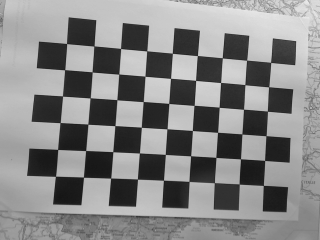
In this section we consider the OpenCV chessboard pattern that has a size of 9 by 6. Each square of the chessboard is 0.025 meters large. We took 5 images called chessboard-01.png, chessboard-02.png, ..., chessboard-05.png. Hereafter we give an example of one of these images.

Snapshot example of the 9 by 6 chessboard used to calibrate the camera.
Before starting the calibration we need to create a configuration file. We create default-chessboard.cfg with the following content:
# Number of inner corners per a item row and column. (square, circle)
BoardSize_Width: 9
BoardSize_Height: 6
# The size of a square in meters
Square_Size: 0.025
# The type of pattern used for camera calibration.
# One of: CHESSBOARD or CIRCLES_GRID
Calibrate_Pattern: CHESSBOARD
# The input image sequence to use for calibration
Input: chessboard-%02d.png
# Tempo in seconds between two images. If > 10 wait a click to continue
Tempo: 1
- Note
- The images and the configuration file used in this tutorial are available in ViSP source code and copied in the same folder than the
calibrate_camera binary.
To estimate the camera parameters, just enter in ViSP <binary_dir>/examples/calibration and run:
./calibrate-camera default-chessboard.cfg
This command will produce the following output:
grid width : 9
grid height: 6
square size: 0.025
pattern : CHESSBOARD
input seq : chessboard-%02d.png
tempo : 1
frame: 1, status: 1, image used as input data
frame: 2, status: 1, image used as input data
frame: 3, status: 1, image used as input data
frame: 4, status: 1, image used as input data
frame: 5, status: 1, image used as input data
Calibration without distorsion in progress on 5 images...
Camera parameters for perspective projection without distortion:
px = 278.5184659 py = 273.9720502
u0 = 162.1161106 v0 = 113.1789595
Global reprojection error: 0.2784261067
Camera parameters without distortion successfully saved in "camera.xml"
Calibration with distorsion in progress on 5 images...
Camera parameters for perspective projection with distortion:
px = 276.3370556 py = 271.9804892
u0 = 162.3656808 v0 = 113.4484506
kud = 0.02739893948
kdu = -0.02719442967
Global reprojection error: 0.2602153289
Camera parameters without distortion successfully saved in "camera.xml"
Estimated pose on input data 0: 0.1004079988 0.07228624926 0.2759094615 0.1622201484 -0.04594748279 -3.067523182
Estimated pose on input data 1: 0.1126235389 0.09590025615 0.2967542475 0.5743609549 -0.1960511892 -2.915893698
Estimated pose on input data 2: 0.09983133876 0.08044014071 0.2920209765 -0.02917708148 -0.6751719307 3.046437745
Estimated pose on input data 3: 0.07481330068 0.0832284992 0.2825482261 -0.09487329058 -0.220597075 -2.747906623
Estimated pose on input data 4: 0.08061439562 0.08765353523 0.2837166409 0.1009190234 -0.09325252997 -2.906079819
The resulting parameters are also saved in ./camera.xml file.
Calibration from a circles grid
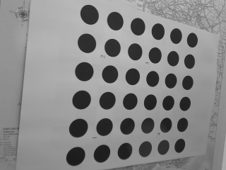
In this section we consider the ViSP symmetric circles grid pattern that has a size of 6 by 6. Each circle center of gravity is 0.034 meters distant from it's horizontal or vertical neighbor. We took 5 images called circles-01.pgm, circles-02.pgm, ..., circles-05.pgm. Hereafter we give an example of such an image.

Snapshot example of the symmetric circles grid used to calibrate the camera.
Before starting the calibration we need to create a configuration file. We create circles-grid.cfg with the following content:
# Number of inner corners per a item row and column. (square, circle)
BoardSize_Width: 6
BoardSize_Height: 6
# The size of a square in meters
Square_Size: 0.034
# The type of pattern used for camera calibration.
# One of: CHESSBOARD or CIRCLES_GRID
Calibrate_Pattern: CIRCLES_GRID
# The input image sequence to use for calibration
Input: circles-%02d.pgm
# Tempo in seconds between two images. If > 10 wait a click to continue
Tempo: 1
- Note
- The images and the configuration file used in this tutorial are available in ViSP source code and copied in the same folder than the
calibrate_camera binary.
To estimate the camera parameters, just enter in ViSP <binary_dir>/examples/calibration and run:
./calibrate-camera circles-grid.cfg
This command will produce the following output:
grid width : 6
grid height: 6
square size: 0.034
pattern : CIRCLES_GRID
input seq : circles-%02d.png
tempo : 1
frame: 1, status: 1, image used as input data
frame: 2, status: 1, image used as input data
frame: 3, status: 1, image used as input data
frame: 4, status: 1, image used as input data
frame: 5, status: 1, image used as input data
Calibration without distorsion in progress on 5 images...
Camera parameters for perspective projection without distortion:
px = 276.7844987 py = 273.2284128
u0 = 164.029061 v0 = 113.2926414
Global reprojection error: 0.3245572722
Camera parameters without distortion successfully saved in "camera.xml"
Calibration with distorsion in progress on 5 images...
Camera parameters for perspective projection with distortion:
px = 272.6576029 py = 268.9209423
u0 = 163.3267494 v0 = 112.9548567
kud = 0.03132515383
kdu = -0.03098719022
Global reprojection error: 0.2985458516
Camera parameters without distortion successfully saved in "camera.xml"
Estimated pose on input data 0: -0.08883802146 -0.07573082723 0.254649414 0.009277810667 -0.1162730223 -0.06217958144
Estimated pose on input data 1: -0.03031929668 -0.07792577124 0.226777101 0.04390110018 -0.474640394 0.09584680839
Estimated pose on input data 2: 0.02757364367 -0.08075508106 0.2416734821 0.2541005213 -0.469141926 0.5746851856
Estimated pose on input data 3: -0.08528071 -0.0552184701 0.216359278 0.433944401 -0.01692119727 -0.01151973247
Estimated pose on input data 4: -0.1104723502 -0.0854285443 0.2684946566 0.4130829919 0.1926077657 0.2736623762
The resulting parameters are also saved in ./camera.xml file.
Distorsion removal
Once the camera is calibrated, you can remove the distortion in the images. The following example available in tutorial-undistort.cpp shows how to do it.
#include <visp3/core/vpImageTools.h>
#include <visp3/core/vpXmlParserCamera.h>
#include <visp3/io/vpImageIo.h>
int main()
{
try {
#ifdef VISP_HAVE_XML2
std::cout << "Cannot found parameters for camera named \"Camera\"" << std::endl;
}
#else
#endif
std::cout << cam << std::endl;
std::cout << "Catch an exception: " << e << std::endl;
}
return 0;
}
In this example we first load the image chessboard.pgm
Then we read the camera parameters with distortion of a camera named "Camera" from libxml2 3rd party support.
#ifdef VISP_HAVE_XML2
std::cout << "Cannot found parameters for camera named \"Camera\"" << std::endl;
}
If vpXmlParserCamera is not available (this may occur if ViSP was not build with libxml2), we initialize the camera parameters "by hand" using the following code:
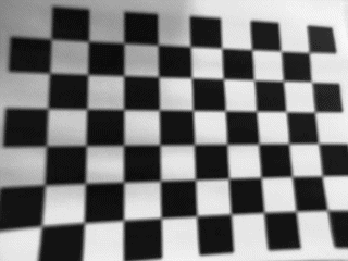
Finally, we create a new image Iud where distortion is removed. This image is saved in chessboard-undistort.pgm.
The resulting chessboard-undistort.pgm image is the following.

chessboard-undistort.pgm image where distortion was removed.
Next tutorial
You are now ready to see the Tutorial: Camera extrinsic calibration that will explain how to estimate the eye-in-hand transformation when the camera is mounted on a robot end-effector.


 the position of a pixel in the digitized image, this position is related to the corresponding coordinates
  in the normalized space.
![\[ \begin{array}{l} u = u_0 + x p_x (1+k_{ud} r^2) \\ v = v_0 + y p_y (1+k_{ud} r^2) \end{array} \]](form_1187.png)

![\[ \begin{array}{l} x = (u-u_0)*(1+k_{du} r^2)/p_x \\ y = (v-v_0)*(1+k_{du} r^2)/p_y \end{array} \]](form_1188.png)

 where:
 are the coordinates of the principal point in pixel;
 are the ratio between the focal length and the size of a pixel;
 are the parameters used to correct the distortion.
  is the distortion parameter used to transform the coordinates from undistorted to distorted images, while
  is used to transform the coordinates from distorted to undistorted images.

