Visual Servoing Platform  version 3.6.1 under development (2024-04-25)
Tutorial: Planar object pose estimation using RGB-D data.

Introduction

Note that all the material (source code and data) described in this tutorial is part of ViSP source code (in tutorial/computer-vision folder) and could be found in https://github.com/lagadic/visp/tree/master/tutorial/computer-vision.

This tutorial which source code is available in tutorial-pose-from-planar-object.cpp shows a way to estimate the pose (cMo) of a planar object pose exploiting color and depth images using a RGB-D camera and the object 3D model.

To illustrate this capability, we will use the next image to estimate the pose of the white object delimited by the orange crosses from 1 to 4. The coordinates of these four crosses define the CAD model of our object. They are expressed in the frame visible in the following image. This object is lying on a larger plane delimited by the blue rectangle that corresponds to the Realsense cover box. The coordinates of the plane bounds are expressed in the same frame.
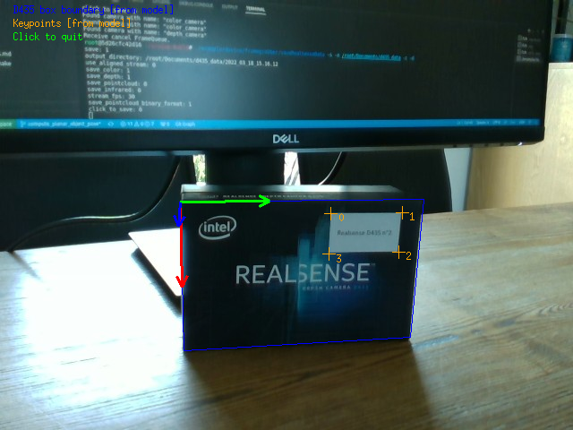
HeTo resume:

  • The origin of the object frame is located at the top left corner of the D435 box.
  • The blue lines represent the box boundary that define the plane to which the object belongs.
  • The orange crosses represent some keypoints that define the object for which pose will be estimated.

In this tutorial, an Intel D435 was used to capture the data. Furthermore, we created a 3D CAD model file available in data/d435_box.model that contains the coordinates of the plane bounds and the coordinates of the object corners.

# Bounds
# - Contains a list of 3D points (X Y Z) corresponding to the bounds of the plane to consider
Bounds
data:
  - [0,          0, 0]    # pt 0: top left point
  - [0,      0.143, 0]    # pt 1: top right point
  - [0.091,  0.143, 0]
  - [0.091,      0, 0]

# Keypoints
# - Contains a list of 3D points (X Y Z) corresponding to the keypoints
# - These points are defined in origin frame and represent the white sticker corners
Keypoints
data:
  - [0.008, 0.086, 0]
  - [0.008, 0.130, 0]
  - [0.033, 0.130, 0]
  - [0.033, 0.086, 0]

Those data are loaded such as:

auto [color_img, depth_raw, color_param, depth_param, depth_M_color] =
readData(vpIoTools::getParent(argv[0]) + "/data/d435_not_align_depth", 0);
const auto model = Model(vpIoTools::getParent(argv[0]) + "/data/d435_box.model");
static std::string getParent(const std::string &pathname)
Definition: vpIoTools.cpp:2086
Note
This example works with color image aligned to depth image or with color image not aligned with depth image.

Finally, in order to compute the object pose, we need:

  • The object plane defined into the color frame [Step 1]
  • Some color image point [pixel] matched with 3D model point [meter] [Step 2]
  • Compute pose estimation [Step 3]

Step 1: Depth-based plane estimation

The first step is to estimate the object plane thanks to the depth data. In this tutorial, the user has to delimitate this area such as:

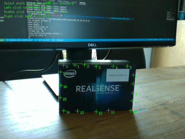
Then, based on the user selected points, a convex hull is created and projected to the depth frame.

vpPolygon roi_color_img {};
roi_color_img.buildFrom(getRoiFromUser(color_img), true);
std::vector<vpImagePoint> roi_corners_depth_img {};
std::transform(
cbegin(roi_color_img.getCorners()), cend(roi_color_img.getCorners()), std::back_inserter(roi_corners_depth_img),
std::bind((vpImagePoint(*)(const vpImage<uint16_t> &, double, double, double, const vpCameraParameters &,
const vpImagePoint &)) &
depth_raw, DepthScale, 0.1, 0.6, depth_param, color_param, depth_M_color.inverse(), depth_M_color,
std::placeholders::_1));
const vpPolygon roi_depth_img { roi_corners_depth_img };
Generic class defining intrinsic camera parameters.
static vpImagePoint projectColorToDepth(const vpImage< uint16_t > &I_depth, double depth_scale, double depth_min, double depth_max, const vpCameraParameters &depth_intrinsics, const vpCameraParameters &color_intrinsics, const vpHomogeneousMatrix &color_M_depth, const vpHomogeneousMatrix &depth_M_color, const vpImagePoint &from_pixel)
Implementation of an homogeneous matrix and operations on such kind of matrices.
Class that defines a 2D point in an image. This class is useful for image processing and stores only ...
Definition: vpImagePoint.h:82
Definition of the vpImage class member functions.
Definition: vpImage.h:69
Defines a generic 2D polygon.
Definition: vpPolygon.h:97
void buildFrom(const std::vector< vpImagePoint > &corners, const bool create_convex_hull=false)
Definition: vpPolygon.cpp:190

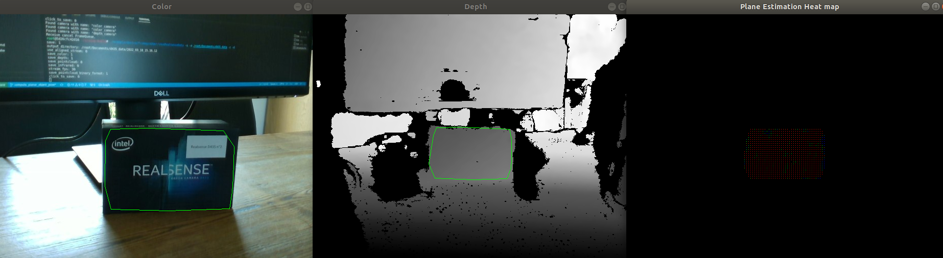
Once, the plane ROI is defined on the depth frame, the plane is estimated. Firstly in the depth frame. Then, the depth-frame-located plane is projected to the color frame.

const auto obj_plane_in_depth =
vpPlaneEstimation::estimatePlane(depth_raw, DepthScale, depth_param, roi_depth_img, 1000, heat_map);
if (!obj_plane_in_depth) {
return EXIT_FAILURE;
}
// Get the plane in color frame
auto obj_plane_in_color = *obj_plane_in_depth;
obj_plane_in_color.changeFrame(depth_M_color.inverse());

Step 2: Image point and model point matching

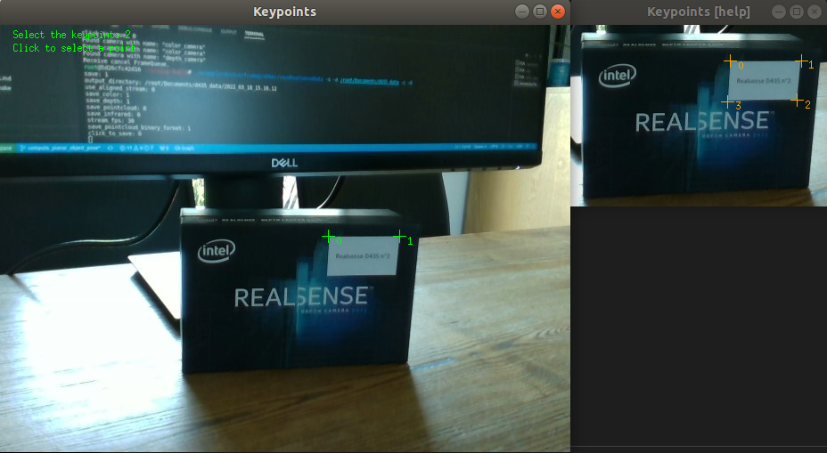
Here, the user is simulating an automatic corner detection and the detection/model matching.

Step 3: Pose estimation

Finally, the object pose (i.e., the relation ship between the object and the color optical frame) is computed thanks to:

const auto cMo = vpPose::computePlanarObjectPoseWithAtLeast3Points(obj_plane_in_color, model.keypoints(),
keypoint_color_img, color_param);
if (!cMo) {
return EXIT_FAILURE;
}

Next tutorial

You can continue with the Tutorial: Pose estimation from points or with the Tutorial: Homography estimation from points.