|
Visual Servoing Platform
version 3.5.0 under development (2022-02-15)
|
|
Visual Servoing Platform
version 3.5.0 under development (2022-02-15)
|
This tutorial focuses estimation of the homogeneous transformation between the robot end-effector and the camera frame. As a use case, we will consider in this tutorial the case of a Panda robot in its research version from Franka Emika equipped with an Intel Realsense SR300 camera mounted on its end-effector. The principle of the extrinsic calibration is easy to apply to any other robot equipped with any other camera attached to the robot end-effector.
Let us consider:
 the homogeneous transformation between the robot base frame (also called fixed frame) and the robot end-effector
 the homogeneous transformation between the camera frame and a calibration grid frame (also called object frame), typically the OpenCV chessboard
 the homogeneous transformation between the end-effector and the camera frame. This is the transformation corresponding to the extrinsic eye-in-hand transformation that we have to estimate.
The calibration process described in this tutorial consists in three stages:
poses and images of the chessboard pose of the chessboard from the images corresponding to couple of poses
  the last step is to estimate the transformation.
Note that all the material (source code) described in this tutorial is part of ViSP source code (in tutorial/calibration folder) and could be downloaded using the following command:
$ svn export https://github.com/lagadic/visp.git/trunk/tutorial/calibration
To get good calibration results follow these Recommendations.
In order to compute the pose from the chessboard image, there is the need to get the camera intrinsic parameters. Depending on the device, these parameters are part of the device SDK or firmware. This is for example the case for our SR300 camera considered in this tutorial. These intrinsic parameters could be retrieved using vpRealSense2::getCameraParameters().
If you have an other camera, or if you want to have a better estimation than the factory parameters you may follow Tutorial: Camera intrinsic calibration. Otherwise you can skip this section.
Download and print a black and white chessboard [OpenCV_Chessboard.pdf].
Glue the chessboard on a flat surface and put it under the camera.
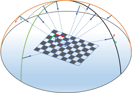
The objective here is to complete step 1. by acquiring couples of poses and the corresponding images of the chessboard. To this end move the camera attached to the robot to different positions. At least 8 to 10 positions are requested. To define a good position you have to imagine a half sphere over the chessboard and select positions that discretise as much as possible all the half sphere surface. For each position you should see all the chessboard as large as possible in the image.
The following image shows a set of 10 camera positions covering the half sphere over the chessboard. Each blue arrow represents camera z-axis pointing to a region close to the chessboard center. The orientation of the frame attached to the chessboard doesn't matter. The chessboard z-axis could be going upward or not.
If you have a Franka robot, follow Configure Ethernet and Connect to Franka desk instructions to power on the Panda robot. Then if this is not already done, follow Install Franka library and Configure and build ViSP.
Connect the Realsense SR300 camera to the computer, put the chessboard in the camera field of view, enter in tutorial/calibration folder and run tutorial-franka-acquire-calib-data binary to acquire the image and the corresponding robot end-effector position:
$ cd tutorial/calibration
$ ./tutorial-franka-acquire-calib-data
By default the robot controller IP is 192.168.1.1. If your Franka has an other IP (let say 10.0.0.2) use --ip option like:
$ ./tutorial-franka-acquire-calib-data --ip 10.0.0.2
Click with the left mouse button to acquire data. It records the following outputs:
camera.xml : XML file that contains the intrinsic camera parameters extracted from camera firmwareimage-<number>.png + pose-fMe-<number>.txt with number starting from 1. pose-fMe-<number>.yaml is the pose of the end-effector expressed in the robot base frame , while image-<number>.png is the image captured at the corresponding robot position.Move the robot to an other position such as the chessboard remains in the image and repeat data acquisition by a left mouse click. We recommend to acquire data at 8 to 10 different robot positions.
A right mouse click ends this step exiting the binary.
This is the output when 8 different positions are considered:
$ ./tutorial-franka-acquire-calib-data
Image size: 640 x 480
Found camera with name: "Camera"
Save: image-1.png and pose_fPe_1.yaml
Save: image-2.png and pose_fPe_2.yaml
Save: image-3.png and pose_fPe_3.yaml
Save: image-4.png and pose_fPe_4.yaml
Save: image-5.png and pose_fPe_5.yaml
Save: image-6.png and pose_fPe_6.yaml
Save: image-7.png and pose_fPe_7.yaml
Save: image-8.png and pose_fPe_8.yaml
The source code corresponding to the binary is available in tutorial-franka-acquire-calib-data.cpp. If your setup is different, it could be easily adapted to your robot or camera.
Here we will complete step 2. by computing for each image the corresponding pose of the chessboard using the camera intrinsic parameters recorded in camera.xml file.
To this end run camera_pose binary to compute the pose of the chessboard with respect to the camera frame. Here we consider that the size of the each chessboard square is 0.027 by 0.027 meter. Modify option --square_size according to your chessboard.
$ ./tutorial-chessboard-pose --square_size 0.027 --input image-%d.png
It produces as output the corresponding poses pose-cMo-<number>.yaml.
$ ./tutorial-chessboard-pose --square_size 0.027 --input image-%d.png
Parameters:
chessboard_width=9
chessboard_height=6
chessboard_square_size=0.027
input_filename=image-%d.png
intrinsic_file=camera.xml
camera_name=Camera
Found camera with name: "Camera"
cam:
Camera parameters for perspective projection with distortion:
  px = 620.9260254   py = 620.9261475
  u0 = 315.6608887   v0 = 238.5752258
  kud = -0
  kdu = 0

Save pose_cPo_1.yaml
Save pose_cPo_2.yaml
Save pose_cPo_3.yaml
Save pose_cPo_4.yaml
Save pose_cPo_5.yaml
Save pose_cPo_6.yaml
Save pose_cPo_7.yaml
Save pose_cPo_8.yaml
The source code corresponding to the binary is available in tutorial-chessboard-pose.cpp.
The final step 3. consists now to estimate the transformation from the couples of and poses.
Complete the calibration running tutorial-hand-eye-calibration binary. It will get the data from the pair of file, pose_fPe_d.yaml and pose_cPo_d.yaml located in ./ folder respectively.
$ ./tutorial-hand-eye-calibration --data-path .
It produces as output the end-effector to camera frame transformation in eMc.yaml and eMc.txt files.
$ ./tutorial-hand-eye-calibration --data-path .
vpIoTools::path(data_path + "/" + file_cPo)
** Hand-eye (eMc) transformation estimated:
-0.005742676471  -0.9978489581  -0.06530297456  0.05345567035
0.9993569641  -0.003415469108  -0.03569303616  -0.009516983454
0.03539321866  -0.06546595596  0.9972269194  -0.04510223842
0  0  0  1
** Corresponding pose vector: 0.05345567035  -0.009516983454  -0.04510223842  -0.0234728216  -0.07938837693  1.574587196

** Translation [m]: 0.05345567035 -0.009516983454 -0.04510223842
** Rotation (theta-u representation) [rad]: -0.0234728216  -0.07938837693  1.574587196
** Rotation (theta-u representation) [deg]: -1.344893611 -4.548618941 90.21720083
** Rotation (quaternion representation) [rad]: -0.01055785589  -0.03570815036  0.7082346124  0.7049944634

Save transformation matrix eMc as a vpPoseVector in eMc.yaml
The result of the calibration is available in eMc.yaml file that contains the as a pose vector, with translation in meter and rotation as a  vector with values in radians.
$ more eMc.yaml
rows: 6
cols: 1
data:
  - [0.0535119]
  - [-0.00910301]
  - [-0.0460504]
  - [-0.0232433]
  - [-0.0802543]
  - [1.57725]
The source code corresponding to the binary is available in tutorial-hand-eye-calibration.cpp.
Since ViSP 3.3.1 we provide hand_eye_calibration_show_extrinsics.py python script that allows to display camera poses used to acquire data. Prior to use that script, you need to install scipy and pyyaml:
$ sudo apt install python-pip
$ pip install scipy pyyaml matplotlib
To visualize camera poses:
$ python hand_eye_calibration_show_extrinsics.py --ndata 8 --eMc_yaml eMc.yaml
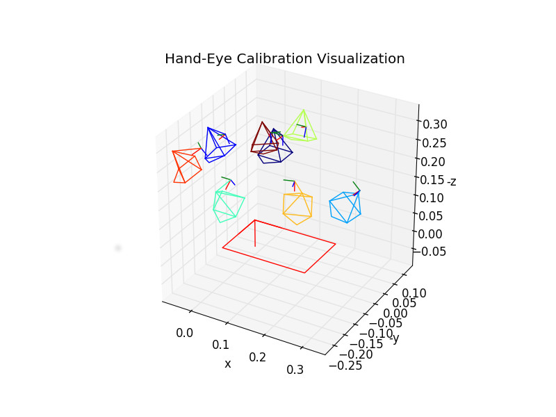
We recall, that a good hand-eye calibration is obtained when the camera poses are covering the surface of a half sphere over the grid.
You are now ready to follow Tutorial: PBVS with Panda 7-dof robot from Franka Emika.
 1.8.13