|
Visual Servoing Platform
version 3.4.0
|
|
Visual Servoing Platform
version 3.4.0
|
This tutorial focuses on pose estimation from planar or non planar points. From their 2D coordinates in the image plane, and their corresponding 3D coordinates specified in an object frame, ViSP is able to estimate the relative pose between the camera and the object frame. This pose is returned as an homogeneous matrix cMo. Note that to estimate a pose at least four points need to be considered.
In this tutorial we assume that you are familiar with ViSP blob tracking. If not, see Tutorial: Blob tracking.
Note that all the material (source code and image) described in this tutorial is part of ViSP source code and could be downloaded using the following command:
In this section we consider the case of four planar points. An image processing done by our blob tracker allows to extract the pixel coordinates of each blob center of gravity. Then using the camera intrinsic parameters we convert these pixel coordinates in meters in the image plane. Knowing the 3D coordinates of the points we then estimate the pose of the object.
The corresponding source code also provided in tutorial-pose-from-points-image.cpp is the following.
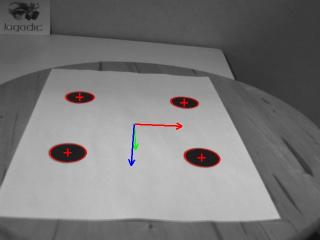
Here is a screen shot of the resulting program:
And here is the detailed explanation of some lines introduced in the source code.
First we include the header pose_helper.h that contains helper functions dedicated to pose estimation.
In pose_helper.h header we include the vpPoint header class that is a container for 3D points with their 3D coordinates in the object frame, and their 2D coordinates in the image plane obtained after perspective projection. These 3D and 2D coordinates will be used as input in the pose estimation algorithm implemented in vpPose class. Then we include the vpCameraParameters header class that contains the camera intrinsic parameters. These parameters are typically used to convert coordinates of a blog cog obtained in pixels from the tracking of the blob, into 2D coordinates expressed in the image plane. The next header concerns the vpHomogeneousMatrix class that is a pose container. Finally, the vpDot2 header class corresponds to the tracker that will be used to track the 4 blobs.
If we have a look in pose_helper.cpp we will find the computePose() function that does the pose estimation. This function uses as input two vectors. The first one is a vector of vpPoint that contains the 3D coordinates in meters of a point, while the second one is a vector of vpImagePoints that contains the 2D coordinates in pixels of a blob center of gravity. The 3D and 2D coordinates of the points need to be matched. That means that point[i] and ip[i] should refer to the same physical point. Other inputs are cam that corresponds to the camera intrinsic parameters, and init that indicates if the pose needs to be initialized the first time. We have cMo [in/out] parameter that is as input the pose estimated from the previous image, and, as output the resulting pose estimated from the input points.
In the computePose() function, we create first an instance of the vpPose class. Then we convert each coordinates of the blob center of gravityip` in 2D coordinates (x,y) in meter in the image plane using vpPixelMeterConversion::convertPoint(). We update then the point instance with the corresponding 2D coordinates and add this point to the vpPose class. Once all the points are added, we can estimate the pose. If init is true, we estimate a first pose using vpPose::DEMENTHON and vpPose::LAGRANGE linear approaches that don't require an initialization. We then compute the residual and select the linear pose estimation result that is the best regarding the residual. The retained pose is used as initialization for the vpPose::VIRTUAL_VS (virtual visual servoing) non linear approach that will converge to the solution with a lower residue than on of the linear approaches. If init is false, we consider that the previous pose cMo is near the solution so that it can be uses as initialization for the non linear visual servoing minimization.
If we come back in tutorial-pose-from-points-image.cpp in the main() function, instead of using an image sequence of the object, we consider always the same image square.pgm. In this image we consider a 12cm by 12 cm square. The corners are represented by a blob. Their center of gravity correspond to a corner position. This gray level image is read thanks to:
After the instantiation of a window able to display the image and at the end the result of the estimated pose as a pose frame, we setup the camera parameters. We consider here the following camera model  where
where  are the ratio between the focal length and the size of a pixel, and where the principal point
  is located at the image center position.
Each blob is then tracked using a vector of four vpDot2 trackers. To avoid human interaction, we initialize the tracker with a pixel position inside each blob. Here we also instanciate a vector of vpImagePoint ip that will be updated in the while loop with the 2D coordinates in pixels of the blob center of gravity.
We also define the 3D model of our 12cm by 12cm square by setting the 3D coordinates of the corners in an object frame located in this example in the middle of the square. We consider here that the points are located in the plane  .
.
Next, we created an homogeneous matrix cMo that will contain the estimated pose.
In the infinite loop, at each iteration we read a new image (in this example it remains the same), display its content in the window, track each blob and update the coordinates of the center of gravity in ip vector.
Then we call the pose estimation function `computePose() presented previously. It uses the 3D coordinates of the points defined as our model in the object frame, and their corresponding 2D positions in the image obtained by the blob tracker to estimate the pose cMo. This homogeneous transformation gives the position of the object frame in the camera frame.
The resulting pose is displayed as an RGB frame in the window overlay. Red, green and blue colors are for X, Y and Z axis respectively. Each axis is 0.05 meter long. All the drawings are then flushed to update the window content.
At the end of the first iteration, we turn off the init flag that indicates that the next pose estimation could use our non linear vpPose::VIRTUAL_VS estimation method with the previous pose as initial value.
Finally, we interrupt the infinite loop by a user mouse click in the window.
We also introduce a 40 milliseconds sleep to slow down the loop and relax the CPU.
We provide also an other example in tutorial-pose-from-points-live.cpp that works on live images acquired by a camera. Compared to the previous example, we replace the single image reader by one of the frame grabber available in ViSP (see Tutorial: Image frame grabbing).
1. Download and print, a square made of 4 blobs
2. Run the corresponding binary
To get the usage of the binary run:
Have a trial adapting the size of your square:
If your camera is calibrated (see Tutorial: Camera intrinsic calibration), you may use your own camera parameters with something similar to:
If you get the following error:
it means probably that your camera is not detected by the first grabber that is enabled using:
If this is the case we suggest to modify the following lines in tutorial-pose-from-points-live.cpp by uncommenting all the grabber that you don't want to use:
For example, if you want to force OpenCV usage to grab images, uncomment the lines:
After modification, build and run again this binary.
You are now ready to see the next Tutorial: Pose estimation from QRcode that gives a use case.
 1.8.11
