|
ViSP
2.8.0
|
|
ViSP
2.8.0
|
With ViSP it is possible to track an object using its cad model. Considered objects should be modeled by lines or cylinders. The model of the object could be defined in vrml format, or in cao format.
The model-based tracker can consider moving-edges behind the lines of the model (see section Model-based edges tracker). It can also consider keypoints that are detected and tracked on each visible face of the model (see section Model-based KLT tracker). The tracker can also handle moving-edges and keypoints in an hybrid scheme (see section Model-based hybrid tracker).
While the Model-based edges tracker is appropriate to track untextured object, the Model-based KLT tracker is more designed to exploit textured objects with edges that are not really visible. The Model-based hybrid tracker is appropriate to track textured objects with visible edges.
In the following sections, we consider the tracking of a tea box modeled in cao format. To simplify the source code, the tracking is performed on a single image. The extension to a sequence of images or to images acquired from a camera is easy.
The following example that comes from tutorial-mb-edge-tracker.cpp allows to track the tea box using vpMbEdgeTracker class.
The video below shows the result of the tea box model-based edges tracking.
Hereafter is the description of the new lines introduced in this example.
Here we include the header of the vpMbEdgeTracker class that allows to track an object from its cad model by using the moving-edges. The tracker will use image I and the intrinsic camera parameters cam as input.
As output, it will estimate cMo, the pose of the object in the camera frame.
Once the input image teabox.pgm is loaded in I, a window is created and initialized with image I. Then we create an instance of the tracker.
There are then two different ways to initialize the tracker.
teabox.xml input file. The display in the image window of additional drawings in overlay such as the moving edges positions, is then enabled by:
An important setting concerns the visibility test that is used to determine if a face is visible. Note that moving-edges are tracked only on visible faces. Two different visibility tests are implemented; with or without Ogre ray tracing. With the next line, we disable Ogre visibility test.
As illustrated in the following figure, the angle  between the normal of the face and the line going from the camera to the center of gravity of the face is then used to determine if the face is visible.
 degrees. When only moving-edges are used (nor keypoints) and when the object to track is simple like a single box, we suggest as here to disable Ogre visibility test. It will help the tracker to detect as soon as possible new faces when only one face is currently tracked.
 degrees, and disappearing if
  degrees.
Additionally to the visibility test described above, it is also possible to use clipping. Firstly, the algorithm removes the faces that are not visibles, according to the visibility test used, then it will also remove the faces or parts of the faces that are out of the clipping planes. As illustrated in the following figure, different clipping planes can be enabled.
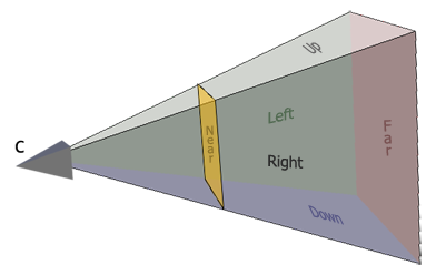
Let's consider two plane categories: the ones belonging to the field of view or FOV (Left, Right, Up and Down), and the Near and Far clipping planes. The FOV planes can be enabled by:
which is equivalent to:
Of course, if the user just wants to activate Right and Up clipping, he will use:
For the Near and Far clipping it is quite different. Indeed, thoses planes require clipping distances. Here there are two choices, either the user uses default values and activate them with:
Or specify the distances in meters, which will automatically activate the clipping for thoses planes:
It is also possible to enable them in the xml file. It should be modified by adding the following lines:
Here for simplicity, the user just has the possibility to either activate all the FOV clipping planes or none of them (fov_clipping requires a boolean).
Now we are ready to load the cad model of the object in cao format with:
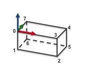
The file teabox.cao describes first the vertexes of the box, then the edges that corresponds to the faces. A more complete description of this file is provided in CAD model in cao format (teabox.cao example). The next figure gives the index of the vertices that are defined in teabox.cao.
Four vertices with their 3D coordinates are then used to initialize the tracker:
The content of teabox.init file is provided hereafter:
We give now the signification of each line of this file:
Here the user has to click on vertex 0, 3, 2 and 5 in the window that displays image I. From the 3D coordinates defined in teabox.init and the corresponding 2D coordinates of the vertices obtained by user interaction a pose is computed that is than used to initialize the tracker.
Next, in the infinite while loop, after displaying the next image, we track the object on a new image I.
The result of the tracking is a pose cMo that could be obtained by:
Next lines are used first to retrieve the camera parameters used by the tracker, then to display the visible part of the cad model using red lines with 2 as thickness, and finally to display the object frame at the estimated position cMo. Each axis of the frame are 0.025 meters long. Using vpColor::none indicates that x-axis is displayed in red, y-axis in green, while z-axis in blue. The thickness of the axis is 3.
The last lines are here to free the memory allocated by libxml2 or Coin 3rd party libraries:
The following example that comes from tutorial-mb-klt-tracker.cpp allows to track the tea box using vpMbKltTracker class.
The video below shows the result of the tea box model-based KLT tracking where keypoints are used as input features.
This example is very similar to the one presented in Model-based edges tracker except that here we use vpMbKltTracker class to track the tea box.
As previously, there are two different ways to initialize the tracker.
teabox.xml file used here contains the following: Note also that in this example we model the tea box with triangles:
The file teabox-triangle.cao describes first the vertexes of the box, then the triangular faces. A more complete description of this file is provided in CAD model in cao format (teabox-triangle.cao example).
Note that this is the only tracker for which lines of the model are not necessary edges of the object.
The following example that comes from tutorial-mb-hybrid-tracker.cpp allows to track the tea box using vpMbEdgeKltTracker class.
The video below shows the result of the tea box model-based hybrid tracking where moving-edges and keypoints are used as input features.
The source code is very similar to the one described in Model-based edges tracker and Model-based KLT tracker. It doesn't require additional line by line explanation. We provide just hereafter the content of the teabox.xml file:
cao format is specific to ViSP. It allows to describe the CAD model of an object using a text file with extension .cao.
The content of the file teabox.cao used in the Model-based edges tracker and Model-based hybrid tracker examples is given here:
This file describes the model of the tea box corresponding to the next image:
We make the choice to describe the faces of the box from the 3D points that correspond to the vertices. We provide now a line by line description of the file:
The content of the file teabox-triangle.cao used in the Model-based KLT tracker example is given here:
This file describes the model of the tea box corresponding to the next image:
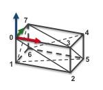
Until line 12, the content of this file is similar to the one described in teabox.cao example. Line 13 we specify that the model contains 12 faces. Each face is then described as a triangle.
 1.8.9.1
