With ViSP it is possible to track an object using its cad model. Considered objects should be modeled by lines, circles or cylinders. The model of the object could be defined in vrml format (except for circles), or in cao format.
Next section highlights the differents versions of the markerless model-based trackers that are implemented in ViSP.
Markerless model-based trackers
The model-based tracker can consider moving-edges behind the lines of the model (see section Model-based edges tracker). It can also consider keypoints that are detected and tracked on each visible face of the model (see section Model-based keypoint tracker). The tracker can also handle moving-edges and keypoints in an hybrid scheme (see section Model-based hybrid tracker).
std::cout << "Catch an exception: " << e << std::endl;
}
#else
(void)argc;
(void)argv;
std::cout << "Install OpenCV or ffmpeg and rebuild ViSP to use this example." << std::endl;
#endif
}
The video below shows the result of the tea box model-based edges tracking.
Hereafter is the description of the new lines introduced in this example.
#include <visp/vpMbEdgeTracker.h>
Here we include the header of the vpMbEdgeTracker class that allows to track an object from its cad model using moving-edges. The tracker will use image I and the intrinsic camera parameters cam as input.
An important setting concerns the visibility test that is used to determine if a face is visible. Note that moving-edges are tracked only on visible faces. Two different visibility tests are implemented; with or without Ogre ray tracing. The default test is the one without Ogre. The function vpMbEdgeTracker::setOgreVisibilityTest() allow to select which test is to use.
Let us now highlight how the visibility test works. As illustrated in the following figure, the angle between the normal of the face and the line going from the camera to the center of gravity of the face is used to determine if the face is visible. If we consider two parameters; the angle to determine if a face is appearing , and the angle to determine if the face is disappearing , a face will be considered as visible if . We consider also that a new face is appearing if . These two parameters can be set either in the xml file:
When these two angle parameters are not set, their default values set to 89 degrees are used.
Principle of the visibility test used to determine if a face is visible.
When Ogre visibility test is disabled (we recall that this is the default behavior), the algorithm that computes the normal of the face is very simple. It makes the assumption that faces are convex and oriented counter clockwise. Here the face is considered as appearing if degrees, and disappearing if degrees. When only moving-edges are used (nor keypoints) and when the object to track is simple like a single box, we suggest as here to disable Ogre visibility test.
When Ogre visibility test is enabled, the algorithm used to determine the visibility of a face is the same than previously except that once visible faces are detected thanks to their normal, we add an other test to reject faces that are partially occluded by an other one. This additional test is performed using Ogre ray-tracing capability.
Additionally to the visibility test described above, it is also possible to use clipping. Firstly, the algorithm removes the faces that are not visibles, according to the visibility test used, then it will also remove the faces or parts of the faces that are out of the clipping planes. As illustrated in the following figure, different clipping planes can be enabled.
Camera field of view and clipping planes.
Let's consider two plane categories: the ones belonging to the field of view or FOV (Left, Right, Up and Down), and the Near and Far clipping planes. The FOV planes can be enabled by:
For the Near and Far clipping it is quite different. Indeed, thoses planes require clipping distances. Here there are two choices, either the user uses default values and activate them with:
It is also possible to enable them in the xml file. This is done with the following lines:
<conf>
...
<face>
...
<near_clipping>0.1</near_clipping>
<far_clipping>100.0</far_clipping>
<fov_clipping>0</fov_clipping>
</face>
Here for simplicity, the user just has the possibility to either activate all the FOV clipping planes or none of them (fov_clipping requires a boolean).
Note
When clipping parameters are not set in the xml file, nor in the code, clipping is not used. Usually clipping is not helpful when the oject to track is simple.
Now we are ready to load the cad model of the object. ViSP supports cad model in cao format or in vrml format. The cao format is a particular format only supported by ViSP. It doesn't require an additional 3rd party rather then vrml format that require Coin 3rd party. We load the cad model in cao format with:
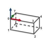
The file teabox.cao describes first the vertices of the box, then the edges that corresponds to the faces. A more complete description of this file is provided in teabox.cao example. The next figure gives the index of the vertices that are defined in teabox.cao.
To load the cad model in vrml the user has to replace the previous line by the following:
As for the cao format, teabox.wrl describes first the vertices of the box, then the edges that corresponds to the faces. A more complete description of this file is provided in teabox.wrl example.
Index of the vertices used to model the tea box in cao format.
Once the model of the object to track is loaded, with the next line the display in the image window of additional drawings in overlay such as the moving edges positions, is then enabled by:
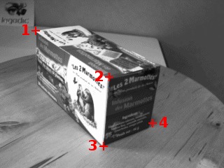
The user has to click in the image on four vertices with their 3D coordinates defined in the "teabox.init" file. The following image shows where the user has to click.
Image "teabox.ppm" used to help the user to initialize the tracker.
Matched 2D and 3D coordinates are then used to compute an initial pose used to initialize the tracker. Note also that the third optional argument "true" is used here to enable the display of an image that may help the user for the initialization. The name of this image is the same as the "*.init" file except the extension that sould be ".ppm". In our case it will be "teabox.ppm".
The content of teabox.init file that defines 3D coordinates of some points of the model used during user intialization is provided hereafter. Note that all the characters after character '#' are considered as comments.
1 4 # Number of points
2 0 0 0 # Point 0
3 0.165 0 0 # Point 3
4 0.165 0 -0.08 # Point 2
5 0.165 0.068 -0.08 # Point 5
We give now the signification of each line of this file:
line 1: Number of 3D points that should be defined in this file. At least 4 points are required. Four is the minimal number of points requested to compute a pose.
line 2: Each point is defined by its 3D coordinates. Here we define the first point with coordinates (0,0,0). In the previous figure it corresponds to vertex 0 of the tea box. This point is also the origin of the frame in which all the points are defined.
line 3: 3D coordinates of vertex 3.
line 4: 3D coordinates of vertex 2.
line 5: 3D coordinates of vertex 5.
Here the user has to click on vertex 0, 3, 2 and 5 in the window that displays image I. From the 3D coordinates defined in teabox.init and the corresponding 2D coordinates of the vertices obtained by user interaction a pose is computed that is than used to initialize the tracker.
Next, in the infinite while loop, after displaying the next image, we track the object on a new image I.
Next lines are used first to retrieve the camera parameters used by the tracker, then to display the visible part of the cad model using red lines with 2 as thickness, and finally to display the object frame at the estimated position cMo. Each axis of the frame are 0.025 meters long. Using vpColor::none indicates that x-axis is displayed in red, y-axis in green, while z-axis in blue. The thickness of the axis is 3.
The file teabox-triangle.cao describes first the vertices of the box, then the triangular faces. A more complete description of this file is provided in teabox-triangle.cao example).
Note that this is the only tracker for which lines of the model are not necessary edges of the object.
std::cout << "Catch an exception: " << e << std::endl;
}
#else
(void)argc;
(void)argv;
std::cout << "Install OpenCV and rebuild ViSP to use this example." << std::endl;
#endif
}
The video below shows the result of the tea box model-based hybrid tracking where moving-edges and keypoints are used as input features.
The source code is very similar to the one described in Model-based edges tracker and Model-based keypoint tracker. It doesn't require additional line by line explanation. We provide just hereafter the content of the teabox.xml file:
<?xml version="1.0"?>
<conf>
<ecm>
<mask>
<size>5</size>
<nb_mask>180</nb_mask>
</mask>
<range>
<tracking>8</tracking>
</range>
<contrast>
<edge_threshold>10000</edge_threshold>
<mu1>0.5</mu1>
<mu2>0.5</mu2>
</contrast>
</ecm>
<sample>
<step>4</step>
<nb_sample>250</nb_sample>
</sample>
<klt>
<mask_border>5</mask_border>
<max_features>300</max_features>
<window_size>5</window_size>
<quality>0.015</quality>
<min_distance>8</min_distance>
<harris>0.01</harris>
<size_block>3</size_block>
<pyramid_lvl>3</pyramid_lvl>
</klt>
<camera>
<u0>325.66776</u0>
<v0>243.69727</v0>
<px>839.21470</px>
<py>839.44555</py>
</camera>
<face>
<angle_appear>70</angle_appear>
<angle_disappear>80</angle_disappear>
<near_clipping>0.1</near_clipping>
<far_clipping>100</far_clipping>
<fov_clipping>1</fov_clipping>
</face>
</conf>
How to model the objects to track
ViSP supports two different ways to describe CAD models, either in cao or in vrml format.
cao format is specific to ViSP. It allows to describe the CAD model of an object using a text file with extension .cao.
vrml format is supported only if Coin 3rd party is installed. This format allows to describe the CAD model of an object using a text file with extension .wrl.
18 4 0 1 2 3 # Face 0: [number of points] [index of the 3D points]...
19 4 1 6 5 2
20 4 4 5 6 7
21 4 0 3 4 7
22 4 5 4 3 2
23 4 0 7 6 1 # Face 5
24 # 3D cylinders
25 0 # Number of cylinders
26 # 3D circles
27 0 # Number of circles
This file describes the model of the tea box corresponding to the next image:
Index of the vertices used to model the tea box in cao format.
We make the choice to describe the faces of the box from the 3D points that correspond to the vertices. We provide now a line by line description of the file. Notice that the characters after the '#' are considered as comments.
line 1: Header of the .cao file
line 3: The model is defined by 8 3D points. Here the 8 points correspond to the 8 vertices of the tea box presented in the previous figure. Thus, next 8 lines define the 3D points coordinates.
line 4: 3D point with coordinate (0,0,0) corresponding to vertex 0 of the tea box. This point is also the origin of the frame in which all the 3D points are defined.
line 5: 3D point with coordinate (0,0,-0.08) corresponding to vertex 1.
line 6 to 11: The other 3D points corresponding to vertices 2 to 7 respectively.
line 13: Number of 3D lines defined from two 3D points. It is possible to introduce 3D lines and then use these lines to define faces from these 3D lines. This is particularly useful to define faces from non-closed polygons. For instance, it can be used to specify the tracking of only 3 edges of a rectangle. Notice also that a 3D line that doesn't belong to a face is always visible and consequently always tracked.
line 15: Number of faces defined from 3D lines. In our teabox example we decide to define all the faces from 3D points, that is why this value is set to 0.
line 17: The number of faces defined by a set of 3D points. Here our teabox has 6 faces. Thus, next 6 lines describe each face from the 3D points defined previously line 4 to 11. Notice here that all the faces defined from 3D points corresponds to closed polygons.
line 18: First face defined by 4 3D points, respectively vertices 0,1,2,3. The orientation of the face is counter clockwise by going from vertex 0 to vertex 1, then 2 and 3. This fixes the orientation of the normal of the face going outside the object.
line 19: Second face also defined by 4 points, respectively vertices 1,6,5,2 to have a counter clockwise orientation.
line 20 to 23: The four other faces of the box.
line 25: Number of 3D cylinders describing the model. Since we model a simple box, the number of cylinders is 0.
line 27: Number of 3D circles describing the model. For the same reason, the number of circles is 0.
18 3 0 1 2 # Face 0: [number of points] [index of the 3D points]...
19 3 0 2 3
20 3 0 3 7
21 3 3 4 7
22 3 4 5 6
23 3 4 6 7
24 3 1 6 5
25 3 1 5 2
26 3 5 3 2
27 3 5 4 3
28 3 7 6 1
29 3 7 1 0 # Face 11
30 # 3D cylinders
31 0 # Number of cylinders
32 # 3D circles
33 0 # Number of circles
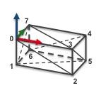
This file describes the model of the tea box corresponding to the next image:
Index of the vertices used to model the tea box in cao format with triangles.
Until line 15, the content of this file is similar to the one described in teabox.cao example. Line 17 we specify that the model contains 12 faces. Each face is then described as a triangle.
teabox.wrl example
The content of the teabox.wrl file used in the Model-based edges tracker is given hereafter. This content is to make into relation with teabox.cao described in teabox.cao example.
1 #VRML V2.0 utf8
2
3 DEF fst_0 Group {
4 children [
5
6 # Object "teabox"
7 Shape {
8
9 geometry DEF cube IndexedFaceSet {
10
11 coord Coordinate {
12 point [
13 0 0 0 ,
14 0 0 -0.08,
15 0.165 0 -0.08,
16 0.165 0 0 ,
17 0.165 0.068 0 ,
18 0.165 0.068 -0.08,
19 0 0.068 -0.08,
20 0 0.068 0 ]
21 }
22
23 coordIndex [
24 0,1,2,3,-1,
25 1,6,5,2,-1,
26 4,5,6,7,-1,
27 0,3,4,7,-1,
28 5,4,3,2,-1,
29 0,7,6,1,-1]}
30 }
31
32 ]
33 }
This file describes the model of the tea box corresponding to the next image:
Index of the vertices used to model the tea box in vrml format.
We provide now a line by line description of the file where the faces of the box are defined from the vertices:
line 1 to 10: Header of the .wrl file.
line 13 to 20: 3D coordinates of the 8 tea box vertices.
line 34 to 29: Each line describe a face. In this example, a face is defined by 4 vertices. For example, the first face join vertices 0,1,2,3. The orientation of the face is counter clockwise by going from vertex 0 to vertex 1, then 2 and 3. This fixes the orientation of the normal of the face going outside the object.
Advanced: How to manipulate the model
The following code shows how to access to the CAD model
to check if a face is visible,
to get the name of the face (only with models in .cao format for the moment)
to check if the level of detail is enable/disable (only with models in .cao format for the moment)
to access to the coordinates of the 3D points used to model a face
from the pose cMo estimated by the tracker to compute the coordinates of the 3D points in the image
The level of detail (LOD) consists in introducing additional constraints to the visibility check to determine if the features of a face have to be tracked or not. Two parameters are used
the line length (in pixel)
the area of the face (in pixel²), that could be closed or not (you can define an open face by adding all the segments without the last one which closes the face)
The tracker allows to enable/disable the level of detail concept using vpMbTracker::setLod() function. This example permits to set LOD settings to all elements :
The first thing to do is to declare the differents points. Then you define each segment of the face with the index of the start point and with the index of the end point. Finally, you define the face with the index of the segments which constitute the face.
Note
The way you declare the face segments (clockwise or counter clockwise) will determine the direction of the normal of the face and so will influe on the visibility of the face.
V1
# Left wing model
6 # Number of points
# 3D points
-4 -3.8 0.7
-6 -8.8 0.2
-12 -21.7 -1.2
-9 -21.7 -1.2
0.8 -8.8 0.2
4.6 -3.8 0.7
# 3D lines
6 # Number of lines
0 1 # line 0
1 2
2 3
3 4
4 5
5 0 # line 5
# Faces from 3D lines
1 # Number of faces defined by lines
6 0 1 2 3 4 5 # face 0: [number of lines] [index of the lines]...
# Faces from 3D points
0
# 3D cylinders
0
# 3D circles
0
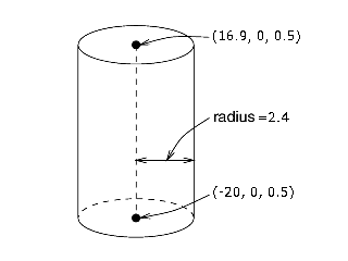
How to model cylinders
The first thing to do is to declare the two points defining the cylinder axis of revolution. Then you declare the cylinder with the index of the points that define the cylinder axis of revolution and with the cylinder radius.
Note
For the level of detail, in a case of a cylinder, this is taking into account by using the length of the axis of revolution to determine the visibility.
Example of a cylinder.
V1
# Cylinder model
2 # Number of points
# 3D points
16.9 0 0.5 # point 0
-20 0 0.5 # point 1
# 3D lines
0
# Faces from 3D lines
0
# Faces from 3D points
0
# 3D cylinders
1 # Number of cylinders
0 1 2.4 # cylinder 0: [1st point on revolution axis] [2nd point on revolution axis] [radius]
# 3D circles
0
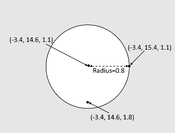
How to model circles
The first thing to do is to declare three points: one point for the center of the circle and two points on the circle plane (i.e. not necessary located on the perimeter of the circle but on the plane of the circle). Then you declare your circle with the radius and with index of the three points.
Note
The way you declare the two points on the circle plane (clockwise or counter clockwise) will determine the direction of the normal of the circle and so will influe on the visibility of the circle. For the level of detail, in a case of a circle, this is taking into account by using the area of the bounding box of the circle to determine the visibility.
Example of a circle.
V1
# Circle model
3 # Number of points
# 3D points
-3.4 14.6 1.1 # point 0
-3.4 15.4 1.1
-3.4 14.6 1.8 # point 2
# 3D lines
0
# Faces from 3D lines
0
# Faces from 3D points
0
# 3D cylinders
0
# 3D circles
1 # Number of circles
0.8 0 2 1 # circle 0: [radius] [circle center] [1st point on circle plane] [2nd point on circle plane]
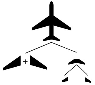
How to create an hierarchical model
It could be useful to define a complex model instead of using one big model file with all the declaration with different sub-models, each one representing a specific part of the complex model in a specific model file. To create an hierarchical model, the first step is to define all the elementary parts and then regroup them.
Example of a possible hierarchical modelling of a plane.
For example, if we want to have a model of a plane, we could represent as elementary parts the left and right wings, the tailplane (which is constituted of some other parts) and a cylinder for the plane fuselage. The following lines represent the top model of the plane.
V1
# header
# load the different parts of the plane
load("wings.cao") # load the left and right wings
load("tailplane.cao")
# 3D points
2 # Number of points
16.9 0 0.5
-20 0 0.5
# 3D lines
0
# Faces from 3D lines
0
# Faces from 3D points
0
# 3D cylinders
1 # Number of cylinders
0 1 2.4 # define the plane fuselage as a cylinder
# 3D circles
0
Note
The path to include another model can be expressed as an absolute or a relative path (relative to the file which includes the model).
It could be useful to give a name for a face in a model in order to easily modify his LOD parameters for example, or just for debuging purpose. This is done directly in the model file :
V1
# header
# load the different parts of the plane
load("wings.cao")
load("tailplane.cao")
# 3D points
5 # Number of points
16.9 0 0.5
-20 0 0.5
-3.4 14.6 1.1
-3.4 15.4 1.1
-3.4 14.6 1.8
# 3D lines
0
# Faces from 3D lines
0
# Faces from 3D points
0
# 3D cylinders
1 # Number of cylinders
0 1 2.4 name=plane_fuselage
# 3D circles
1 # Number of circles
0.8 2 4 3 name="right reactor"
Note
If the name contains space characters, it must be surrounded by quotes. You can give a name to all the elements excepts for points.
How to tune the level of detail
As explained in section Advanced: Level of detail (LOD) the parameters of the lod can be set in the source code. They can also be set directly in the configuration file or in the CAD model in cao format.
The following lines show the content of the configuration file :
The order you call the methods to load the configuration file and to load the CAD model in the code will modify the result of the LOD parameters. Basically, the LOD settings expressed in configuration file will have effect on all the elements in the CAD model while the LOD settings expressed in CAD model will be specific to an element. The natural order would be to load first the configuration file and after the CAD model.
 between the normal of the face and the line going from the camera to the center of gravity of the face is used to determine if the face is visible. If we consider two parameters; the angle to determine if a face is appearing
  , and the angle to determine if the face is disappearing
  , a face will be considered as visible if
  . We consider also that a new face is appearing if
  . These two parameters can be set either in the xml file:
  degrees, and disappearing if
  degrees. When only moving-edges are used (nor keypoints) and when the object to track is simple like a single box, we suggest as here to disable Ogre visibility test.
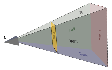
 1.8.9.1
