Table of Contents
Introduction
Various authors have proposed different formulations of the pose estimation problem which does not require the need of markers or keypoints matching process.
In ViSP such an algorithm is proposed. It allows to track an object using its cad model. Considered objects should be modeled by lines, circles or cylinders. The model of the object could be defined in vrml format, or in cao format. The markerless model-based tracker considered here can handle moving-edges behind the contour of the model.
The video below shows the result of a tea box model-based tracking.
Source code
The following source code also available in pose-mbt-visp.cpp allows to compute the pose of the camera wrt. the object that is tracked.
Source code explained
Hereafter is the description of the most important lines in this example.
Here we include the header of the vpMbEdgeTracker class that allows to track an object from its cad model using moving-edges. The tracker will use image I and the intrinsic camera parameters cam as input.
As output, it will estimate cTw, the pose of the object in the camera frame.
Once the input image teabox.pgm is loaded in I, a window is created and initialized with image I. Then we create an instance of the tracker.
There are then two different ways to initialize the tracker.
- The first one, if libxml2 is available, is to read the settings from
teabox.xmlinput file if the file exists.The content of the xml file is the following:if(vpIoTools::checkFilename(objectname + ".xml")) {tracker.loadConfigFile(objectname + ".xml");usexml = true;}<?xml version="1.0"?><conf><ecm><mask><size>5</size><nb_mask>180</nb_mask></mask><range><tracking>8</tracking></range><contrast><edge_threshold>10000</edge_threshold><mu1>0.5</mu1><mu2>0.5</mu2></contrast></ecm><sample><step>4</step><nb_sample>250</nb_sample></sample><camera><u0>325.66776</u0><v0>243.69727</v0><px>839.21470</px><py>839.44555</py></camera></conf> - The second one consists in initializing the parameters directly in the source code: vpMe me;me.setMaskSize(5);me.setMaskNumber(180);me.setRange(8);me.setThreshold(10000);me.setMu1(0.5);me.setMu2(0.5);me.setSampleStep(4);me.setNbTotalSample(250);tracker.setMovingEdge(me);cam.initPersProjWithoutDistortion(839, 839, 325, 243);tracker.setCameraParameters(cam);
Now we are ready to load the cad model of the object. ViSP supports cad model in cao format or in vrml format. The cao format is a particular format only supported by ViSP. It doesn't require an additional 3rd party rather then vrml format that require Coin 3rd party.
First we check if the file exists, then we load the cad model in cao format with:
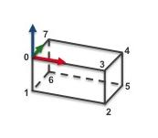
The file teabox.cao describes first the vertices of the box, then the edges that corresponds to the faces. A more complete description of this file is provided in CAD model in cao format. The next figure gives the index of the vertices that are defined in teabox.cao.
If the cad model in cao format doesn't exist, we check then if it exists in vrml format before loading:
As for the cao format, teabox.wrl describes first the vertices of the box, then the edges that corresponds to the faces. A more complete description of this file is provided in CAD model in vrml format.
Once the model of the object to track is loaded, with the next line the display in the image window of additional drawings in overlay such as the moving edges positions, is then enabled by:
Now we have to initialize the tracker. With the next line we choose to use a user interaction.
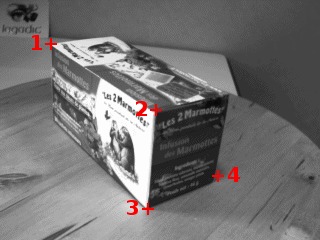
The user has to click in the image on four vertices with their 3D coordinates defined in the "teabox.init" file. The following image shows where the user has to click.
Matched 2D and 3D coordinates are then used to compute an initial pose used to initialize the tracker. Note also that the third optional argument "true" is used here to enable the display of an image that may help the user for the initialization. The name of this image is the same as the "*.init" file except the extension that sould be ".ppm". In our case it will be "teabox.ppm".
The content of teabox.init file that defines 3D coordinates of some points of the model used during user intialization is provided hereafter. Note that all the characters after character '#' are considered as comments.
We give now the signification of each line of this file:
- line 1: Number of 3D points that should be defined in this file. At least 4 points are required. Four is the minimal number of points requested to compute a pose.
- line 2: Each point is defined by its 3D coordinates. Here we define the first point with coordinates (0,0,0). In the previous figure it corresponds to vertex 0 of the tea box. This point is also the origin of the frame in which all the points are defined.
- line 3: 3D coordinates of vertex 3. - line 4: 3D coordinates of vertex 2.
- line 5: 3D coordinates of vertex 5.
Here the user has to click on vertex 0, 3, 2 and 5 in the window that displays image I. From the 3D coordinates defined in teabox.init and the corresponding 2D coordinates of the vertices obtained by user interaction a pose is computed that is than used to initialize the tracker.
Next, in the infinite while loop, after displaying the next image, we track the object on a new image I.
The result of the tracking is a pose cTw that could be obtained by:
Next lines are used first to retrieve the camera parameters used by the tracker, then to display the visible part of the cad model using red lines with 2 as thickness, and finally to display the object frame at the estimated position cTw. Each axis of the frame are 0.025 meters long. Using vpColor::none indicates that x-axis is displayed in red, y-axis in green, while z-axis in blue. The thickness of the axis is 3.
Object modeling
CAD model in cao format
cao format is specific to ViSP. It allows to describe the CAD model of an object using a text file with extension .cao. The content of the file teabox.cao used in this example is given here:
This file describes the model of the tea box corresponding to the next image:
We make the choice to describe the faces of the box from the 3D points that correspond to the vertices. We provide now a line by line description of the file. Notice that the characters after the '#' are considered as comments.
- line 1: Header of the
.cao file - line 3: The model is defined by 8 3D points. Here the 8 points correspond to the 8 vertices of the tea box presented in the previous figure. Thus, next 8 lines define the 3D points coordinates.
- line 4: 3D point with coordinate (0,0,0) corresponding to vertex 0 of the tea box. This point is also the origin of the frame in which all the 3D points are defined.
- line 5: 3D point with coordinate (0,0,-0.08) corresponding to vertex 1.
- line 6 to 11: The other 3D points corresponding to vertices 2 to 7 respectively.
- line 13: Number of 3D lines defined from two 3D points. It is possible to introduce 3D lines and then use these lines to define faces from these 3D lines. This is particularly useful to define faces from non-closed polygons. For instance, it can be used to specify the tracking of only 3 edges of a rectangle. Notice also that a 3D line that doesn't belong to a face is always visible and consequently always tracked.
- line 15: Number of faces defined from 3D lines. In our teabox example we decide to define all the faces from 3D points, that is why this value is set to 0.
- line 17: The number of faces defined by a set of 3D points. Here our teabox has 6 faces. Thus, next 6 lines describe each face from the 3D points defined previously line 4 to 11. Notice here that all the faces defined from 3D points corresponds to closed polygons.
- line 18: First face defined by 4 3D points, respectively vertices 0,1,2,3. The orientation of the face is counter clockwise by going from vertex 0 to vertex 1, then 2 and 3. This fixes the orientation of the normal of the face going outside the object.
- line 19: Second face also defined by 4 points, respectively vertices 1,6,5,2 to have a counter clockwise orientation.
- line 20 to 23: The four other faces of the box.
- line 25: Number of 3D cylinders describing the model. Since we model a simple box, the number of cylinders is 0.
- line 27: Number of 3D circles describing the model. For the same reason, the number of circles is 0.
CAD model in vrml format
ViSP support vrml format only if Coin 3rd party is installed. This format allows to describe the CAD model of an object using a text file with extension .wrl. The content of the teabox.wrl file used in this example is given hereafter. This content is to make into relation with teabox.cao described in CAD model in cao format.
This file describes the model of the tea box corresponding to the next image:
We provide now a line by line description of the file where the faces of the box are defined from the vertices:
- line 1 to 10: Header of the
.wrl file. - line 13 to 20: 3D coordinates of the 8 tea box vertices.
- line 34 to 29: Each line describe a face. In this example, a face is defined by 4 vertices. For example, the first face join vertices 0,1,2,3. The orientation of the face is counter clockwise by going from vertex 0 to vertex 1, then 2 and 3. This fixes the orientation of the normal of the face going outside the object.