|
Visual Servoing Platform
version 3.1.0
|
|
Visual Servoing Platform
version 3.1.0
|
This tutorial describes how to use the generic model-based tracker. You are advised to have read these tutorials:
The main motivations for the introduction of this new class (vpMbGenericTracker) are:
In this perspective, this class can be used instead of the following classes:
Moreover, the features can be combined to improve the tracking robustness (e.g. a stereo tracker with edge + KLT for the left camera and dense depth features for the right camera).
The following video demonstrates the use of the generic tracker with a RGB-D sensor using the following features:
In this video, the same setup is used but with:
Note that all the material (source code and video) described in this tutorial is part of ViSP source code and could be downloaded using the following command:
The basis type of features that can be used with the model-based tracker are:
The moving-edges and KLT features require a RGB camera, more precisely these features operate on grayscale image. The depth normal and dense depth features require a depth map that can be obtained from a RGB-D camera for example.
If you want to use a depth feature, we advise you to choose the dense depth features that is a much more robust method compared to the depth normal feature. Keep in mind also that Kinect-like sensors have a limited depth range (from ~0.8m to ~3.5m).
There are 3 choices for the alternative libblas.so.3 (providing /usr/lib/libblas.so.3).
Selection Path Priority Status 0 /usr/lib/openblas-base/libblas.so.3 40 auto mode 1 /usr/lib/atlas-base/atlas/libblas.so.3 35 manual mode 2 /usr/lib/libblas/libblas.so.3 10 manual mode 3 /usr/lib/openblas-base/libblas.so.3 40 manual mode
For classical features working on grayscale image, you have to use the following data type:
You can convert to a grayscale image if the image acquired is in RGBa data type:
For depth features, you need to supply a pointcloud, that means a 2D array where each element contains the X, Y and Z coordinate in the depth sensor frame. The following data type are accepted:
3x1 (X, Y, Z) If you have only a depth map, a 2D array where each element is the distance in meter between the depth sensor frame to the object, you will need to compute the 3D coordinates using the depth sensor intrinsic parameters. For instance, without taking into account the distortion (see also vpPixelMeterConversion::convertPoint), the conversion is (u and v are the pixel coordinates, u0, v0, px, py are the intrinsic parameters):
![\[ \left\{\begin{matrix} X = \frac{u - u_0}{px} \times Z \\ Y = \frac{v - v_0}{px} \times Z \end{matrix}\right. \]](form_1217.png)
Here an example of a depth map:
Each tracker is stored in a map, the key corresponding to the name of the camera on which the tracker will process. By default, the camera names are set to:
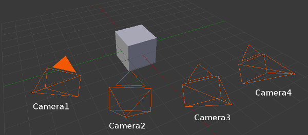
To deal with multiple cameras, in the virtual visual servoing control law we concatenate all the interaction matrices and residual vectors and transform them in a single reference camera frame to compute the reference camera velocity. Thus, we have to know the transformation matrix between each camera and the reference camera.
For example, if the reference camera is "Camera1" (  ), we need the following information:
  .
.
The following enumeration (vpMbGenericTracker::vpTrackerType) values are available to get the desired model-based tracker:
The tracker declaration is then:
To combine the features:
To "fully exploit" the capabilities of a RGB-D sensor, you can use for instance:
This will declare a tracker with edge + KLT features for the color camera and dense depth feature for the depth sensor.
Each essential method used to initialize the tracker and process the tracking have three signatures in order to ease the call to the method and according to three working modes:
The following table sums up how to call the different methods based on the camera configuration for the main functions.
| Method calling example: | Monocular case | Stereo case | Multiple cameras case | Remarks |
|---|---|---|---|---|
| Construct a model-based edge tracker: | vpMbGenericTracker tracker | vpMbGenericTracker tracker(2, vpMbGenericTracker::EDGE_TRACKER) | vpMbGenericTracker tracker(5, vpMbGenericTracker::EDGE_TRACKER) | The default constructor corresponds to a monocular edge tracker. |
| Load a configuration file: | tracker.loadConfigFile("config.xml") | tracker.loadConfigFile("config1.xml", "config2.xml") | tracker.loadConfigFile(mapOfConfigFiles) | Each tracker can have different parameters (intrinsic parameters, visibility angles, etc.). |
| Load a model file: | tracker.loadModel("model.cao") | tracker.loadModel("model1.cao", "model2.cao") | tracker.loadModel(mapOfModelFiles) | Different models can be used. |
| Get the intrinsic camera parameters: | tracker.getCameraParameters(cam) | tracker.getCameraParameters(cam1, cam2) | tracker.getCameraParameters(mapOfCam) | |
| Set the transformation matrix between each camera and the reference one: | tracker.setCameraTransformationMatrix(mapOfCamTrans) | tracker.setCameraTransformationMatrix(mapOfCamTrans) | For the reference camera, the identity homogeneous matrix must be used. | |
| Setting to display the features: | tracker.setDisplayFeatures(true) | tracker.setDisplayFeatures(true) | tracker.setDisplayFeatures(true) | This is a general parameter. |
| Initialize the pose by click: | tracker.initClick(I, "f_init.init") | tracker.initClick(I1, I2, "f_init1.init", "f_init2.init") | tracker.initClick(mapOfImg, mapOfInitFiles) | Assuming the transformation matrices between the cameras have been set, some init files can be omitted as long as the reference camera has an init file. The corresponding images must be supplied. |
| Track the object: | tracker.track(I) | tracker.track(I1, I2) | tracker.track(mapOfImg) | See the documentation to track with pointcloud. |
| Get the pose: | tracker.getPose(cMo) | tracker.getPose(c1Mo, c2Mo) | tracker.getPose(mapOfPoses) | tracker.getPose(cMo) will return the pose for the reference camera in the stereo/multiple cameras configurations. |
| Display the model: | tracker.display(I, cMo, cam, ...) | tracker.display(I1, I2, c1Mo, c2Mo, cam1, cam2, ...) | tracker.display(mapOfImg, mapOfPoses, mapOfCam, ...) |
The following example comes from tutorial-mb-generic-tracker-stereo-mono.cpp and allows to track a tea box modeled in cao format.
Once built, to choose which tracker to use, run the binary with the following argument:
The config, model, init files should be named according to the video name: teabox.mpg / teabox.cao / teabox.xml / teabox.init
The source code is the following:
The previous source code shows how to use the new vpMbGenericTracker class as a replacement of the classical classes. The procedure to configure the tracker remains the same:
Please refer to the tutorial Tutorial: Markerless model-based tracking in order to have explanations about the configuration parameters (Tracker settings) and how to model an object in a ViSP compatible format (CAD model in cao format).
The required include is:
We need a grayscale image for the tracking:
To set the type of the tracker (the first parameter is the number of cameras, the second parameter is the type of the tracker(s)):
To load the configuration file, we use:
Otherwise you can parameter the tracker directly in the code:
To load the 3D object model, we use:
We can also use the following setting that enables the display of the features used during the tracking:
The initial pose is set by clicking on specific points in the image:
The tracking is done by:
To get the current camera pose:
To display the model with the estimated pose:
The following example comes from tutorial-mb-generic-tracker-stereo.cpp and allows to track a tea box modeled in cao format using a stereo rig.
Once built, to choose which tracker to use, run the binary with the following argument:
The config, model, init files should be named according to the video name: teabox_left.mpg / teabox_left.cao / teabox_left.xml / teabox_left.init, ...
The procedure is almost identical to the monocular case.
The include is:
Two images are needed:
To set the types of the tracker:
To load the configuration files, we use:
We have to set the transformation matrices between the cameras and the reference camera to be able to compute the control law in a reference camera frame. In the code we consider the left camera with the name "Camera1" as the reference camera. For the right camera with the name "Camera2" we have to set the transformation (  ). This transformation is read from cRightMcLeft.txt file. Since our left and right cameras are not moving, this transformation is constant and does not need to be updated in the tracking loop:
To load the 3D object model, we use:
We can also use the following setting that enables the display of the features used during the tracking:
The initial poses are set by clicking on specific points in the image:
The tracking is done by:
To get the current camera poses:
To display the model with the estimated poses:
You are now ready to see the next Tutorial: Markerless model-based tracker CAD model editor - GSoC 2017 project.
 1.8.13